ARCHIVE OF REPAIR TRICKS, TROUBLESHOOTING, USEFUL INFO, ETC.
- nu instruments SA-18824, Seren 2000, dead torch box, fried 2KW RF gen.
- Pfeiffer/Balzers turbomolecular pumps 121 and 40 repair notes, 40schematic
- Vacuum Atmospheres Omni-lab glove box, PLC is Mitsubishi FX3S, solenoid fail, buzzing, bad int. relay APAN3124
- Mini-circuits ZHL-5w repair fried front end 04 marking code
- Welch Dry Vacuum Pump "self cleaning," 2025, 2026, 2027, Secret to disassembly (and, bad run-capacitor.)
- Binder EDS56 drying oven 1.tempr reading gone crazy, 2. no pwr
- Linkam LTS420 T96-HS cable pins DB25/Lemo, heated stage
- 700MHz 3.2W amplifier 35dB front end died, SBA-5089Z (ebay/amazon)
- Fisher Isotemp cabinet FBG45, compressor fan repeatedly failed
- Newport TRA 25 PPD motorized actuator, motor hums, doesn't rotate
- Bad Protek PUP110-40-S supply on Nicolet 6700 FTIR
- Vacuum Atmospheres Omni-lab glove box, Mitsubishi Melsec FX1S PLC, fill valve fail, bad int. relay RB104-DE
- Signatone micropositioner, broken triax at brass tube
- Thermo ATQ orbitrap missing +15V -15V
- Axopatch CV-203BU headstage, not cooling, wrong temperature display
- KappaCCD x-ray crystallography controller, missing +5, +-12V
- LS-55 Spectrophotometer Perkin Elmer, stepper errors
- Eppendorf 5415D Centrifuge won't wake up after power-down
- ATQ, LTQ Thermo analog board catches fire, MS1035 supply destroyed (97055-98001)
- AMT/Herley 3205 pulse amplifier 300watt, output clipping over 40Watt
- Thermo SP131325 repair knob shaft, yellow stirplate hot plate Cimarec
- IKA stir motor M1G055-AI01-01
- Thorlabs AO crystal failed, aom EO-AM-NR-C1 EO-PM-NR-C1 EO-AM-NR-C
- Buchi B-490, 491, 495 intermittent power, then dies
- IKA rotovap heat bath HB Basic overheats, boils dry
- Eppendorf 5417 centrifuge, blinking LEDs, supply failed
BLAX300RS, BLAXH50 Bruker NMR amplifiers, various repair notes:
- Hanovia ultraviolet driver blows fuse
- Headstage for Dagan Chem-clamp, output overload (JFET died)
- Mettler XS analytical balance, display frozen
- Solar Light XPS-400 "Solar Simulator"400w xenon lamp driver
- Lesker KJL-205 Vacuum gauge thermocouple gauge
- CM-100 TEM microscope CRT video monitor, distortion
- Epson M-180 printer for Amsco Steris "Eagle" autoclave
- Aspirator pump 7049 Cole-Parmer, pumps backwards
- J-kem vacuum regulator 280, misc. repair info
- Precision Oven, door won't close, broken latch/hinge
- Bruker Avance AQS fans Y.S. Tech, alternate source
- Branson 'Sonifier' W185, converter transducer head
- Corning mag stir hotplate repair
- Glovebox pass-through connectors for USB etc.
- Perkin-Elmer FTIR 1600 and Spectrum RX-1 laser adjust notes
- BLMH60 Bruker amplifier in BLAXH50 NMR repair notes
- KJ Lesker 800 series convection gauge KJL901278 calibrate
- HP59864B mini-ion vacuum gauge repair notes
- IKA RCT stir plate repair notes
- Cary Spectrometer common high voltage supply fail
- Eppendorf minispin centrifuge, door jammed
- Dwyer Photohelic gauge on HE-493 Glovebox
- KNF N920 vacuum pump on Bruker cryoprobe
- Spectrum RX-1 FTIR, printer error, compatible incompatible
- Dead DAC Sipex 9377-16, use` Texas Ins. DAC712
- Fans in BLAH1000, BLAX 300RS Bruker Avance Amp, 80mm 3-wire
- Edwards 507 vacuum gauge dead gauge tube D35501000, also pinouts
- Elba/Artesyn 28V power supply in Bruker Avance BLAX / BLARH
- Elba/Artesyn supply schematics found in databooks
- 455A746 Motor for Thermo model 4631 "Large 3D Rotator"
- BLAX300 Fried 150ohm resistors in Bruker BLMX001 (B-LMX1, BLMX1 ?)
- Bad jacks in Texas Instruments graphing calculators TI-83 etc.
- Spectra-Physics 2018-RM Laser
- Applied Kilovolts K9174 dual HV supply from mass spec
- Edwards Vacuum Valve PV25EK, IV25EK, blows fuse
- Perkin-Elmer FTIR Spectrum RX1, source coil early life fail
- Misc Links
-
vac gauge4-wire tube http://www.televac.com/downloads/datasheets/2A_Thermocouple.pdf
MISC. LINKS
- 128543 Quiktip thermocouple crimps hex $152.00/100
- nickle "TC pressure connectors" 128543 leeds betts honeywell $100.00/100
- (or if you have the tool, just use gold crimp pins from a DB9 connector!)
Thermo SP131325, Repair knob shaft, yellow stirplate hot plate Cimarec
These common yellow stir-plates by Thermo Scientific/Cimarec have
plastic potentiometer shafts, knobs easily broken off.
But Thermo no longer sells the replacement pot assembly! The pots
themselves aren't sold anywhere either. It's an OEM part from CTS
Electrocomponents, with a big plastic spacer and extra-long shaft.
And a power switch.
BUT, we can dissect the broken pot and reconstruct it. Keep the shell,
but use internal parts from other pots.
NEEDED
- Oritinal broken pot, PCB, and knob
-
450D104-8-ND 450K w/removable shaft (digikey)
-
450T328F104A1C1 (digikey CT3059, w/switch)
The long plastic shaft from the 450D104 can be cut down and used to replace
the (too short) metal one on the second pot. And, the rotor-assembly from the
metal one will work inside the original Thermo pot.
Here at Chem Dept. the undergrads occasionally shear off the pot-knobs. Do
we just throw away a perfectly good $500 stirplate?!! We can fix this.
Other repair parts are still available, see
Labequipmentparts.
On the original broken pot, cut the three pot terminals inside the silicone,
desolder the tabs from the small pcb and remove. Then unbend the four tabs on the pot case,
and retreive the thick plastic spacer and threaded tube. Unsolder and
discard the rest of the pot. (Only its thick poly spacer will be used.)
On the CT3059 w/switch, remove the plastic shaft by unbending the tabs and removing
the back cover to get internal access, so you can CAREFULLY pry the shaft-end
out of the plastic rotor. Don't break it!!! Discard the rest.
On the 450D104-8-ND pot, very carefully unbend the four tabs, extract
the rotor assembly, pry out the aluminum shaft and discard it, replacing
it with the long plastic shaft from the CT3059 pot. Reassemble the 450D104
pot, but using the brass threaded tube and thick poly spacer from the
original broken pot.
Mill or drill two slots in the pcb to make it compatible with the new switch-tabs
on the back of the 450D104-8-ND pot. Install that pot on the PCB. Cover the three
conductors with silicone, and seal the slot in the pot case (don't get
any silicone inside the pot!)
Binder drying oven EDS-56 one dead unit, another w/wildly fluctuating LED numbers
Employs an RTD platinum PT100 probe and a PID controller from West-CS.com, MV160M, actually MAXVU16, the version with 120/240VAC supply, SSR out, and two unused relays , see ctrlr https://www.west-cs.com/products/models/maxvu16/,
cheat-sheet manual
also
https://www.binder-world.com/us-en/products/drying-and-heating/product/ed-s-56
One unit no power. Internal thermal fuse is blown (because controller max setting wasn't 200C as expected!) The little ceramic fuse-device is buried in the rear insulation, lower right quadrant, it's a "TCO," Temperature Cut Out, a one-way switch with a bead of lead-alloy which melts at 318C. Pull off the quick discon tabs. Find online, DeLonghi 5213215191 (replacement part for coffee machine, eReplacementParts 155431.006N .) The controller setting was 220C, and if the rear wall exceeded 320C, perhaps the door was opened too long? Or, a large amount of cold material was loaded? Apparently these ovens can die if set above 200C. (Best to change the slow ramp function, see the controller manual. Or, do it manually by setting the temp to 180C initially, then raise the temp much later, once it has stabilized. That way the oven walls won't be higher temp than the sensor probe.)
The other unit had loose internal tabs inside the West-CS PID controller, disassembling and then re-seating the tiny PCB fixed the failure. Also, the SSR on this particular oven becomes far too hot when initially raising the temp (especially if door left open a crack, so it runs continuously.) No replacements in stock here, so I just added a 3"x4" thick aluminum plate to the back, as a heat-spreader. Works fine.
REMOVING THE CONTROLLER Like many PID units, from the front we can pull it out and swap it for identical guts, by prying the top and bottom edge w/screwdriver. That only extracts the pcb and front panel from the controller's shell. Instead to actually remove it, I removed the entire oven top. Push the controller from behind and pop it loose from the red plastic, while using screwdrivers or blades under the red plastic tabs on the two exposed controller faces. (This is easier if you first pry the entire red plastic assy. out from the oven face, pushing in the red tabs from behind.)
  CONTROLLER REAR SCREW TERMINALS

Lt. Blue  6  -  6   Red (AC line)
          5  -  5
          4  -  4
to ssr VI 3  -  3  BU to ssr
          2  -  2  WH  rtd2
  rtd1 RD 1  -  1
Note that the sensor is filtered by the PID algorithm, so startup tempr-reading only changes quite slowly. On the PT100 sensor, typical room temp. here is around 108.9 ohms
Welch Dry Vacuum Pump 2025, 2026, 2027
How to open up the stupid thing?!!! The top and rear are designed to slide backwards, once the six rear screws are removed. But this is almost impossible to do. Perhaps it worked fine, before all the steel panels were painted? Lots of prying finally frees up the top panel so it can slide backwards.

Another failure ...everything runs fine, but no vacuum shown on the meter. (Turn the "vacuum control" fully CW of course, and plug the vac inlet with a fingertip!) The leak was located in the small black hose leading to the pressure gauge, where hose-vibration caused a crack. Cut off the hose at the crack, and it was still long enough to put on the meter-port.
Warning: sometimes no leak exists, and the flap-valves inside the pump's top assembly are all crusty and need cleaning. Or, sometimes the expensive diaphragms have cracked from old age. Then you'll need a Welch diaphragm rebuild kit, it's 2025K01 or 2025K02 for the 2025 model pump.)
Pump won't start? Or, long delay? Often the 15uF "motor-run" capacitor had decayed to 7uF, just barely enough to start the pump (after many, many seconds silent delay.) The motor coils overheat before the pump actually "gets over the hump" and starts spinning. If you don't have an exact replacement capacitor, just temporarily connect another few-uF capacitor in parallel with the existing one (using non-polarized above 220VAC of course.) The pump will then run OK for a few months ...until the value of the original capacitor decreases even more.
Hint: search for ...run capacitor 16uf. Many are available if you search for 16uF rather than 15uF. Make sure it's 36mm diameter (under 1.4in,) otherwise it may not fit inside the pump housing. (Many of these similar capacitors are large, 2in diameter and 400VAC.)
ZHL-5W Mini-circuits 6GHz 5-watt amplifier
Ususally these suffer from a fried front end. Missing 13db of gain, if not simply dead. The mini-circuits marking code for the SOT-89 mmic is "o4" for the GALI-4+ a 60mW 6GHz amplifier, three bucks from digikey.
GHz amplifier module, 3.2W
A little broadband RF amplifier from Amazon. These always die after a few months? They've sanded off the part numbers? So we cannot repair them? The front-end part number is an mmic, (probably a common SBA-5089Z half-watt GHz amplifier, gain of around 20dB.) Currently those chips are going extinct, but still on eBay for cheap. The second component is 12V, 150mA, so it might be an rf MOSFET rather than bipolar.
Linkam LTS420 T96-HS cable pins DB25/Lemo, heated stage
Dead cable connector. 4-pin LEMO, red/blue are 5-ohm heating element, gn/bk are PT100 rtd temp-sensor. RTD element has doubled wires, yl/gn on one side, wh/bk on the other. Heater pins are DB25-4 and -5
DB25 end:
	1,14	 -	to-92 ?temp sensor?
	2	 -	to-92 ?temp sensor?

	3,4	 -	RD, heater to lemo-4 (pin)
	16,17

	5,6	 -	BU, heater to lemo-3 (pin)
	18,19

	12,13	 -	GN,YL rtd to lemo-2 (socket)

	22,25	 -	BK,WH rtd to lemo-1 (socket)
Fisherbrand Isotemp cabinet FBG45CPLA, new fan, bad blades
After a building power-fail, our new sample-chiller heated up to +31C. Compressor is new, fan was just replaced. NEW FAN, SAME FAILURE.
The blade assy came unscrewed from the motor shaft. When line power failed, it tilted, scraped against the fan housing, and could not start up.
All these fans probably fail in the same way: the central screw unscrews itself, because it could not be tightened at the factory. There is no way to hold the motor shaft still. The flatted shaft just chews through the soft plastic, and rotates, so the shaft spins when they tried to tighten the screw. (No metal insert! A poor design.) To repair, I slightly melted the rotor-blades' plastic socket, then "formed" a new flatted-socket by inserting the motor shaft. I added a tiny dot of Crazy Glue to the shaft before mostly screwing down the blades. When glue had hardened, the screw could be tightened.
Note: the temperature controller here is DANFOSS ERC-112C, but Youtube lessons cannot help, because passwords were enabled, and apparently the menus are disabled, reading "non". Cannot change the Alarm high/low temperature values, or enable the alerm function. Default PW is "000" for top level.
KappaCCD controller, Zenith ZPS-45 supply +5V +-12V
X-ray Crystallography unit is dead, the internal LED for +24V is lit, but +-12V, +5V is dark.
The smaller switching supply has no output. It contains a small Zenith
outrigger pc board 204-2533-02D with a dip8 chip "221-466-01 E SG", which
appears to be a common UC3844 pwm switching controller. At power up the vcc between pins 7 and 5 on ICX101 is 16.5VDC, very suspicious, since 16V is the power-up trigger threshold. Yes indeed, the electrolytic filter cap is bad, and isn't providing the needed energy-pulse to initially "bootstrap" the chip into full operation. Replace CX28 (22uF at 35V,) now the chip gets its 17V start-surge, and everything comes alive again.
Thermo mass spec Orbitrap ATQ, missing +/- 15VDC on Temp ctrl PCB
Error reported on Temperature Controller PCB, caused by missing +/- 15VDC supply. On the PCB, the green smt LEDS for +15 and -15 are very dim. Also on the 208 1140 supply itself the green LED appears dim. Voltage measures as 2.7V, pulsing (the supply seems to be constantly resetting.) The actual supply block is hidden on the RIGHT side of the instrument, down near the floor.
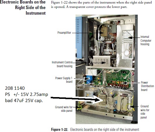
I replaced the two small 47uF electrolytic capacitors (near the TL3842 chip.) The larger 50V device measured OK, but the smaller 47uF 25V cap measured as 7.1uF. Problem solved. So, the cause was capacitor-aging, where the boot-up pulse from the 220VAC resistor chain wasn't long enough to keep the TL3842 device powered through its start sequence, which caused it to reset over and over.
Thermo PN 2081140 208-1140 (208 4440 typo) +-15VDC 2.75Amp, actually is sold by Sunpower SPS-060P-D4 dual 60watt 15V inp: 85-264VAC
IKA stir plate RET Basic
Won't stir. Water spill under motor, destroyed SMT resistors and traces.
IKA partslist gives the part nos. for this model
The main PCB is: IKA part no. 3185001 $305.00 . The motor is: IKA part no. 2869900 $312.00 (motor wo/magnet.)
It's an EBM PAPST 24V DC fan motor, (16-28V-)
Ebmpapst part no.
M1G055-AI01-01, which I don't find in their PDF catalog.
The four pins for the motor electronics are, top view from left to right:
- +24VDC (more like 33V in the stirplate)
- Tachometer out, Hall chip, TTL O.C. output
- V(inp), 0-5VDC gives analog 0-1000RPM.
- Gnd/common
The motor speed-ctrl electronics is digital, with a hcf4093 quad op amp and
an
SG3524 pwm ctrl chip, with 25KHz pwm outputs going to the V(in) motor pin.
Thorlabs AO crystal EO-AM-NR-C1 EO-PM-NR-C1 EO-AM-NR-C
One of our crystal modulators failed, apparently spontaneously. 40MHz drive, only one watt max possible. The driver is fine, but AM modulation is down by two orders. THE CRYSTAL CAPACITANCE IS WRONG, should be around 13pF, but instead much lower.
Apparently one of the gold electrodes has peeled loose from of two lithium-niobate rods. This was a new modulator (well under 1yr old.) Thorlabs simply replaced it wo/question. Opening up an identical modulator-head, I find that the two crystals are gold plated on two sides, but the wire connections lead to a huge solder-pool on each crystal rod, which covers nearly the entire gold-plated side! Yes, if the crytals heat up, either they may come loose from the lower bonding to the heavy heat-sink, or instead, perhaps the expansion of crystal vs. the solder too much differ, and the solder-blob peels the gold foil loose from the crystal surface. (I expect only one of two separate crystals to fail. The expected capacitance will fall to something under 50%. Typical module measurements: 13.5pF, 1.2ohm series loss. If driving it up above 80MHz, crystal heating can easily exceed 1.0W. )
Later incident, Brimrose AO Modulator TEM 110-5-400/1000 shorted input? Nope, just a parallel inductor (3turns.) At 110MHz, the Zin is crazy (680 ohms, not fifty.) When hand-warmed above 27.6C, Zin suddenly drops to 106 ohms. Mechanically sensitive, Zin jumps around when tapped with fingertip. Open the case, and see that the entire crystal has an enormous fracture, in parallel with the base mounting! If the rf drive relies on a bottom contact for ground, then 90% of that contact area has sheared off.
Buchi B-490, 491, 495 heat bath for rotary evaporator
Power becomes intermittent, then fails. Caused by the large "coaxial" power connector on
the bottom of the water tub section. Often there's a bad crimp on the brass tab for the
outer brass ring (the blue neutral conn.) The tiny brass teeth extending through the brass
tab were supposed to be bent wide in those two slots, or even bent around and down. Instead
they're only bent slightly, and the brass tab can rattle around.
The poor crimping eventually causes heating
and even burn marks, until some oxide eventually breaks the connection. Scrape off the crud,
sand the brass a bit, bend the teeth fully outwards, then solder for good measure,
using plenty of flux.
If you buy one of these BUCHI tubs used, you might wish to open up the bottom and solder
the teeth into the brass tab, just to avoid future problems.
IKA HB Basic, heat bath, IKA rotary evaporator
Old HB-10 "Basic" rotovap heat bath is no longer supported by IKA, but they do still sell the
variable thermostat. After years, the 10-amp contacts in this thermostat become
corroded, then rather than opening/closing, they spot-weld together, which turns
the bath temperature to max, and raises the temperature to the safety setting
(or even boils off the contents.)
Buy from IKA: pn: 3883300, Controller, Temp, HB 10 B ($73 in 2017)
Yes the curved temp-sensor capillary does remove from the base of the tub. Shove
the tip to get it started. Push real hard!
Also, notice the tiny screw in the center of the temp-adjust shaft (normally hidden
by the blue knob.) If you require your temperature to be exactly 90C when set to
90, hold the shaft with pilers and slightly tweak the tiny screw (CW moves the
knob setting higher.)
Ace Glass/ Hanovia UV lamp driver 200W 450W
Our lamp-driver for ultraviolet photochemical reactor is blowing fuses.
Not repairable: shorted turns in the transformer.
New price on these is over $2000 in the Ace Glass catalog. These are just Hanovia ballast
transformers for mercury-vapor streetlights. Old ones are
common on eBay for around $150. For 450watt UV bulb, the Hanovia no. 34245 transformer
is 115AC input at 7A max, ~330VAC output O.C., with an output series capacitor of 550V, 22.5uF,
Hanovia no. 32927. In operation, the 450watt mercury-arc lamp draws 3 to 4 Amps and pulls down the AC output
voltage to 135VAC. We typically use
Hanovia quartz/mercury lamp no. PC451.050.
(Yes it's 450watts. The Hanovia list has a typo, and the "45" watts is wrong.) On Ace Glass site
it's 7825-34, $818
Note that there are several models in the current catalog.
The older 7830 supply works for 450watt or 200 watt, and includes a series ballast capacitor. The 100-watt version is transformer-only.
- Ace glass 7830-56, 200 watt
- Ace glass 7830-60, 450 watt
- UV lamp, 450 watt, 9"
- UV lamp, 450 watt, 11"
- List, UV supplies and lamps (.pdf)
- eBay: Ace Glass 7830 supply
XPS-400 "Solar Light," Xenon lamp driver, Solar Simulator
The unit will repeatedly ignite the lamp, but it won't "catch." Not a bad lamp:
a new xenon lamp behaves the same, repeatedly flashing.
Note that to take the case apart, the plastic bezels unsnap. Remove only the front panel
(first remove the switch knob and its set screws.) On the back, remove the top two screws, then slide
the extruded aluminum cover to the front. Note the original alignment of the LCD display
connectors: the upper-right pin and the lower left pin will plug into the far end of each
ribbon connector. Perhaps take photos before unplugging!
Right side of the case is taken up by "Deltron V501D04" DC Power Supply, 24VDC 30A 740W, inp 115V 14A.
I found that the supply had been overheated, with the two capacitors (1200uF 200V) value decreased
by 30%. On the two power transistors, the Molex connectors plugged into their pins were
discolored, and the transistor pins oxidized. So, in the Molex connectors remove and replace the
KK-156 crimp pins, and clean the transistor pins. Replace the two large capacitors with Nichion LGW
series, 1200µF 200V Digikey 493-8523-ND.
The fan airflow design is poor. Much of the airflow is "shorted out," so the front of the
unit doesn't cool enough. I added a barrier of duct tape to the rear half of the upper edge
of the DC power supply, so air won't divert across the case, and must instead flow to the front.
The three large 2200uF 200V capacitors also are aged, with values decreased to 1500uF. However,
the unit started working after only replacing the two 1200uF caps in the Deltron supply, so it looks
like those were the actual cause of failure.
Note that live 120VAC is present on the rear connector pins to the lamp housing cable! This
acts as an interlock: removes AC power from the Deltron 24VDC supply whenever the lamp housing
isn't connected.
MICROPOSITIONER PROBE HEAD SIGNATONE
broken triaxial cable
The triax cables on these get too much bending at the entry to the brass tube, so center conductor breaks at solder joint.
Entire needle-holder tip unscrews (hold with vise, don't lose the PEEK plastic ring and tiny spring-washer,) unsolder coax shields, pull out coax cable and the long center brass narrow rod. (Or, if cable break, push the rod out from the screw-thread probe end.)
Note: BEFORE re-soldering center conductor of triax, strip it to preserve ~5mm of it insulated, push that part through the tan-color PEEK cylinder, otherwise the wire insulation swells up during tinning the strands, forcing you to start over.
Stripped the cable and re-soldered. Carefully align the asymmetrical peek tube that supports the brass rod near the probe end. Both triax shield-braids are soldered to the brass tube. Also added large hotmelt-heatshrink tube to coax end of the brass tube, so this won't just break again.
METTLER-TOLEDO XS104 ANALYTICAL BALANCE
SYMPTOMS: display works, buttons will beep, but no grams display
(just shows a software revision number, like "4.11" )
This indicates that the main scale system is down, and the display terminal cannot make contact. (When the
main scale is working, you should briefly see *TWO* software revision numbers, like "4.11 4.65.")
I disassembled the main scale and pulled out the large square PCB inside the shield box. The problem turned
out to be a fried (open) series inductor on the main +24V incoming power. This was probably caused by
a failure on the -12V switcher, which was running in 100KHz "short circuit mode" rather than 260KHz normal
switching. (Symptom: the output is -12V but only when totally unloaded. Even a 1K resistor placed across -12VDC
pulls it down less than -6V.)
EPSON M-180 PRINTER FOR OLD AUTOCLAVE
Amsco-Steris "Eagle Century"
Ancient dot-matrix paper-tape printer gone crazy, printing unsynched stripes of
distortion, and paper sometimes halting. Steris wants big $$$$$$$$.
One of these I managed to repair under the microscope. The tiny reed-switch was cracked,
so the software can't synch the characters. But Digi-Key stocked a similar part,
14mm reed switch 374-1274-ND, Standex ORD228VL-2030. Soldered in and positioned
carefully to duplicate the original, so the magnet inside the rotating cam will
trigger it. Also, the rubber pinch-roller wasn't rotating because the 90deg angle
plastic gear on the end of its metal shaft wasn't engaging the tooth-ring below
it. The gear had a crack, and had slid outwards towards the shaft end. Pushing
it back would make the printer work for awhile. A tiny bit of crazy glue on the
crack (and on the shaft-end) kept it going for another year.
FOUND THEM!
Barcodes Inc. can get these printers, 4mo backorder.
The actual part number is M100-003203, that's an Epson Impact Printer M-180-031, about $50 in
2014 (buy two, since they wear out before the autoclave does.)
Printer ribbon for this printer: heh no, it's not $42.95 from autoclave suppliers.
Instead try newegg business, epson ERC-22B black ribbon cartridge $7 for two
EYELA A-1000S ASPIRATOR PUMP, ALSO COLE-PARMER 7049-00, BRINKMANN BUCHI B-169 BACKWARDS FLOW
Poor vacuum, and low flow? The failure was caused by a jammed check-valve blocking the
vacuum line for one of the two aspirators. These flap-valves are located inside the
blue plastic connectors to the external hose barbs. To access the failed part, remove the
short rubber hoses which connect just under the main pump platform. Note the plastic
part shaped like a large hexagonal nut. Loosen and unscrew this nut. Inside is
a movable rubber disk which typically swells larger over the years, and either will
block the vacuum port, or will jam in place and fail to block any reverse water-flow.
(An o-ring also is part of this assembly, check it for cracking, and of course don't
misplace it!) To repair, either trim the edge of the rubber disk back to
?1cm?? diameter, or replace it with a fresh disk cut from a thick rubber sheet.
Reverse flow? Internal corrosion! These pumps contain a pair of aspirator pumps (aspirator
tubes) which employ a ball-bearing check-valve inside the "tee" vacuum port in the
brass pump body. If the tip of the small internal jet
corrodes, the ball-bearing can fall into the water outlet, diverting the entire
water-flow into your vacuum line! The unit does include check-valves inside the
upper short hose connections. But these frequently fail because of cracked or
swollen rubber.
The internal jet-assembly for an aspirator tube isn't for sale separately. The Cole-Parmer
part number for each complete aspirator tube is 07049-60, and is still available
as of 2015. Pricy though, under $200 for a pair. I've seen these on eBay. (Nope,
gone now 2016: no longer sold by Cole-Parmer.)
A similar part *might* be Humboldt Mfg, number H12020, also see Chapman Inc.
Also T&S Brass BL-5500. (I haven't
tried these. Are the NPT 3/8" threads compatible?)
One fix is to unscrew the bottom tube assembly from the jet, and discard the ball bearing,
and add an external check-valve to your vacuum hose.
Another temporary fix might be to clean off the jet and solder a heavy piece of wire or two,
placed on the side where the ball-bearing falls through. But probably this will
just corrode away a year later, and again divert liters of water into your vacuum hoses.
Better to just discard the ball bearing and loop the hose upwards 5ft above the pump,
so it takes a fair back-pressure before water can invade. And then add an external one-way
valve to your vacuum line!.
If you find a replacement aspirator, make sure the lower pipe will extend deep under
water. You don't want the liquid jet to make bubbles (which will be sucked
into the pump, filling the fluid loop with foam rather than water.) For
a too-short aspirator assembly, probably a piece of tygon or rubber hose
can be jammed onto the end, so the jet only exits deep below water level
and doesn't entrain air bubbles.
GLOVEBOX PASSTHROUGH FOR USB OR 4-WIRE DATA CABLES
We're using LEMO connectors for getting USB cables into vacuum-tight
gloveboxes. The parts are available from Mouser electronics:
LEMO (threaded feedthrough connector)
Circular push pull connector 4P fixed
coupler, vacuum tested
SWH.1S.304.CLLPV
$87
LEMO (4-pin cable connector, two required)
FFA.1S.304.CLA.C42Z
$41
PRECISION CONVECTION GRAVITY OVEN, DOOR WON'T CLOSE
The door latches eventually fail in these Thermo Scientific "Precision"
gravity ovens. This may be caused by a drooping door, which in turn is
caused by a worn hinge. The metal door grabber latches aren't available,
but a similar plastic version can be found:
C3-805-RS SOUTHCO "Grabber Latch"
from Allied Elect.
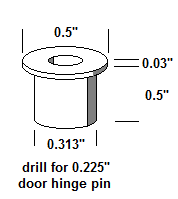
These latches may wear out quickly because of misalignment of the door, which occurs when the brass
inserts for the hinge pins get worn out, causing the door to droop downwards. I haven't tried to find
replacements, instead I just whacked out a few of these with the shop lathe as below. Half-inch
rod stock (brass, or even aluminum,) drilled for a 0.225" pin, then turned down to fit
the 0.315" holes in the oven door.
CORNING MAGNETIC STIRRER HOTPLATE
Replacement bearings are $6.40 each from VXB.com:
SR4AZZ Stainless Bearing, dry, sealed, ID:1/4" OD:3/4", 9/32"
You need the un-greased ones above, otherwise the low-torque AC motor can't turn the stir magnet at low RPM.
Might want to add some light oil though.
Or, a jammed rusted bearing can be cleaned. You'll need a squirt-bottle and rubbing alcohol.
Squirt into the gap, roll the bearing, then slam it on a paper towel on a table, and
see the red rust powder coming out.
Dead "as is" Corning stir plates are cheap on eBay. Usually these are
listed as "heats, won't stir." In that case the bearings are rusted (usually
rusted from using the stir plate in a lab fume hood or glove box with corrosive
vapors.) Swap out the bearings, or clean them, and it's up and running again.
REPLACEMENT FANS FOR BRUKER AQS AVANCE
Can't find FD121225MB or YW12025012BM Chinese Y. S. TECH fans
for console cooling in Bruker Avance NMR? No similar fans with locked-rotor 3rd wire (O.C. output pulls low
during operation, high for alarm) I tried this close match from Digikey, and modified the output:
603-1331-ND FAN AXIAL 120mm X 25.4m 12VDC 3-WIRE (speed sensor tach)
To convert the open-collector tachometer output to locked-rotor alarm output, I added a 10uF 35volt
capacitor from 3rd-wire to gnd, with 33 ohms in series to protect the fan's transistor.
As long as the Bruker pull-up circuit is larger than 3.3K (and 5volt,) the 90Hz tach output shouldn't
give errors. If it does, increase the capacitor to 100uF. Note that the fan itself is 95CFM instead
of 89, and 4 watts instead of 3.5.
Rated 70K hours life instead of 80K. Digikey does sell the correct rubber fan mounts, but
listed under "fan rivet."
EPPENDORF MINISPIN CENTRIFUGE: DOOR STICKING STUCK
The mini-spin centrifuge is vulnerable to tiny amounts of spilled buffer
contamination it its door latch interlock section. The latch needs to return
very quickly when the door comes down, otherwise the motorized wheel will catch
it in a between state and bind permanently. (Permaently! Sometimes temporarily
fixed by giving it a thump, or by using a paperclip to rotate
the interlock wheel via the bottom slot, rotate it one complete turn in either
direction.)
Unfortunately any dried solution down in the shaft/latch will slow its return
motion and let the motorized nylon wheel crash. Quick fix: remove the lid shaft,
open the case (note the position of the lid-lifter and heavy spring.) Then bend
the wire spring which returns the moving latch, bent to greatly increase the return
force. That way it pops rapidly into place after deflection, regardless of
built-up crust. Better fix: take a photo for ref of spring positions, then remove
snap-ring, springs, and disassemble the whole latch part. Don't lose the tiny
snap-ring! I cleaned everything and heavily
greased those rot/slide parts, so perhaps future spilled fluids will be excluded,
and any dried crust will have no effect.
LASER PRINTER ERROR/INCOMPATIBLITIY ON PERKIN-ELMER RX-1 FTIR SPECTROMETERS
This FTIR spectrophotometer is only compatible with certain laser printers. At first we
thought this involved an issue with the printer's PCL command set, and the HP-GL/2
plotter language. Nope.
Intstead I find that the instrument has an apparent design problem on its parallel port:
it ignores the "BUSY" pin and just keeps sending data to the printer. The printer
then freezes up, leaving the "BUSY" pin high. All of our RX-1 units do it.
This doesn't cause problems when using the old HP-1200 laserjet. But
on the modern printer HP P2035 equipped with a parallel port, this behavior causes the
printer to lock up and require a power-off to reset.
We'll try adding an LPT-to-USB smart cable, then try other modern USB laserprinters.
It might only be the HP P2035 which has the "BUSY pin" compatibility issue. See
LPT2USB for
a $70 converter to allow modern printers to be used with Centronics parallel
LPT port found on old instruments.
SIPEX DAC CHIP 9377-16-4 NO LONGER SOLD, BUILT A REPLACEMENT USING TI DAC712
Our old Leybold e-beam controller acts weird: its 24-pin DAC chip is corrupted
and no longer gives trustworthy output voltages. No DAC 9733s to be bought anywhere.
I find that the T.I. DAC712 (digi-key) is fairly close, but different pinout. I can build a
little hand-wired adapter board that carries the DAC712 and plugs into the 9377 socket.
Differences: the /CLR pin needs to pull up to +5, so I add a 4.7V zener and 33K on pin-5
10-volt ref. out of the DAC712. I ground A0 and A1 to make it behave as a transparent
latch. The MSB pin has to be inverted to map the negative values to positive, so I make
a simple inverter for A15 using a 2N3904 transistor. The gain and offset trimmers go on
this little board (the original ones on the main PCB are now unused.)
EDWARDS THERMOCOUPLE VACUUM GAUGE TYPE 507, D35501000 GAUGE TUBE FRIED, NO LONGER SOLD
The gauge-tube finally died on one lab's Edwards 507 tabletop vacuum gauge. Sensor part
no. D35501000 (actually D355-01-000,) with a 5-pin DIN audio connector. Obsolete product,
no longer sold by Edwards, and the last one on eBay was back in 2010. It's a 4-wire type
gauge not the popular 3-wire thermopile Teledyne Hastings DV-6. At full scale (hard
vacuum) it puts out 10mV to the 507 meter, and the meter's drive current to the blown out heater
filament is 5.0Vdc through a 470ohm resistor and a 200ohm trim pot set to 80ohms.
Maybe the
Hastings DV-23 or
KJL-1518 would work? Might need a custom
paper face for the meter-needle. I have a similar 4-wire tube available: the old
Televac "2A"
gauge tube, 2-2100-10, from a Fredericks gauge. It's a 10mV fullscale tube, and this one
has a 6-ohm heater which needs 0.57Vdc and 89mA. The Edwards 507 meter can only suppy
TEN MA for the heater. Rats. Do drive the heater I'll need to add a little AC stepdown
transformer, 120 : 6.3VAC, a Zener to give stable AC volts (two 3.3V zeners back to back
in series, with 30ohm series resistor.) Then connect this to the gauge tube pins 1,8
with series resistors 22ohm and a 50-ohm trimpot. With the sensor pumped down to 10e-3 Torr
vacuum, I can set the trimmer to give zero reading on the meter. Works fine, no other
modifications needed.
REPLACING NMB 3110NL-05W-B59 FANS FOR BRUKER NMR AMPS, BLAH1000, BLAX300RS, ETC.
The three 3-wire 80mm fans in the rack inside various Bruker NMR amplifiers
are no longer available from online suppliers or from the manufacturer NMB. If
your web search finds an NMB 3110NL-05W-B59, it won't be any twelve bucks each!!
Must you buy them from Bruker?
Inspecting the NMB catalog, we find that "N" fans are gone, and are replaced by
identical "K" fans which have a mirror-image rotor blade shape. The max DC drive
current is also 6% higher. The closest match which is widely available is NMB
3110KL-05W-B69-D00, on Digi-key as
P13491, $14 each. That's what we've been using in all our amps. Note that
the "B69" means ballbearing, speed-6, and 3-wires. Don't buy "B60," it's 2-wires.
BAD "ELBA ARTESYN" POWER SUPPLY, BLAX AMPLIFIER, BLARH, BRUKER NMR, MAGNETIC RESONANCE
Bill Beaty (beaty atsign chem washington e d u)
Mon, 10 May 2004 16:07:47 -0700
Rather than paying the $1500, I've managed to repair a bunch of these power
supplies in Bruker BLAX.  Want some info?

First note that these Artesyn or "Elba" 220VAC supplies WILL RUN ON 120VAC.
This makes testing easier.  But I wouldn't recommend drawing a high-wattage
load when the line voltage is so low.

Also note that you need to place a small load on the +15v, -15v, +5v
supplies, and a 10-watt load on the +28V.  If you run them with no load
at all, the switching-supply starts up, but then halts.  Without a load,
the output voltages start out briefly correct, then start falling.  Load
the +28V output with a 47-ohm 10w resistor.  Put 91-ohm 3W on each of
the + and - 15V, and a pair of 15-ohm 2W resistors paralleled on the +5V
line.

On the first supply I repaired, the main bridge rectifier and the big
APT5025 FETs for the 365VDC Power Factor regulation were fried.  These
components sit right on the 220VAC line, so any major surge can kill
them.  The diode bridge is a weird thin little thing under the main PCB,
part number D20XB60, availible from Mouser Electronics, (600V 35amp bridge.)
The MOSFETs were APT5025BN from Advanced Power Technology, advancedpower.com/
http://www.dz98.com/wjj-pdf/apt5025.pdf
I found an actual APT5025BN, but probably a similar transistor would
work, if you can find a TO-247 package for 500V 23A 0.25ohm 300watt,
N-channel, gate threshold max 4v (such as IXFH24N50 or IRFP360
from DigiKey.)

The second dead unit also had a bad NPN transistor from ZETEX which, if
I recall right, drove the gates of the main switching MOSFETS driving the
220AC to 365VDC switcher.  The big MOSFETS were dead, as was the UC3854N
power-factor IC on the soldered-in daughter board next to the 270uF 400V
capacitors. (See below for a schematic that's similar to the
daughter board PF-correction circuit.) There was a fried 22-ohm resistor
below the big ferrite transformer, and a shorted 1N6284A zener across the
28VDC output (located near the middle of three UC3524 chips near the
output terminals.) No doubt a surge on the 220VAC line shorted out one
component, and the large current destroyed everything else.  Be sure to
check the value of that 22-ohm resistor, because if its value becomes far
more than 22 ohms, the regulated 28VDC output voltage can rise greatly.

A third unit had a stalled fan.  The heat had killed the two big 270uF
400V electrolytics.  Also, the values of tiny electrolytics were all wrong
on the soldered-in PF daughter board (the board next to the 270uF 400v
caps.)  I found I could replace all these tiny capacitors without having
to unsolder the many pins of the daughter board.  Be sure to mark the
polarity, since there's no silkscreen plus-signs on that PCB.  These
capacitors are part of a tiny high-freq switching power supply that runs
components on that board, so high temperatures will bake out these capacitors
and make the supply fail during a power-up.  (Apparently the Elba supply can
run almost forever when its fan is dead, but the extra heat slowly ruins
the capacitors critical for power-up sequence.)  I replaced the two 47uF 50v
(a volt doubler) that runs the power factor chip, the 100uF 50V cap on the
corner next to the power transistor, and the two 22uF 35V caps next to
the fan connector (they're essential for the fan's power supply.)


Now our fourth dead unit was very interesting.

There is an apparent design weakness in the 30V section of the "Elba" power
supply used in some versions of the BLAX 300 and similar amps.  When the supply
first comes up, the 30VDC switching regulator chip (UC3825) on the second
daughter board needs at least 9V to wake up and start making DC.  In normal
operation it creates its own supply voltage from its own 30VDC regulated
output... it pulls itself into the sky by its own bootstraps!  But during
startup, it temporarily needs another supply.  It gets this from a little
"bootstrap power supply winding" on that big iron tapewound inductor in the
center of the PCB which is part of the power-factor switching circuit.
This winding is voltage-doubled with two diodes and three capacitors (two 10uF,
one 220uF, partly hidden under a transformer,) making 20VDC, which supplies
a LM7812 regulator, which supposedly puts out 12VDC for the UC3825 chip.  But
the UC3825 draws 33mA, which can drag the 12v supply voltage of the
bootstrap/LM7812 down to 8.9V...   and sometimes the UC3825 goes into continuous
repeating reset and never starts.  It's waiting for its bootstrap-supply to rise
up above 9.0V.  This all depends on temperature and on many component values.
This is possibly bad design?  They should have given plenty of leeway (like
designing it to actually put out 12VDC, even when it draws 33mA as it does.)

Regarding the idea that heat can kill these supplies...  yep, if any of the
three small electrolytic capacitors next to the LM7812 regulator in the voltage-
doubler bootstrap supply should get baked out, so their capacitance value
drops, or their internal leakage gets large...   then these changes will
push things over the edge.  The UC3825 on the pluggable daughter board at
the edge of the main board never gets its 12VDC, and the supply cannot wake
itself up anymore.

      The usual symptom: your system was running for many days or weeks,
      but then after being switched off, or after a building power failure,
      it won't wake back up again.

(But sometimes, if you switch it off and back on more than once, it will
"catch," and start running.)  Our dead supply had a 220uF 50V electrolytic
capacitor (next to the LM7812) which had changed itself to 20uF over the years.
When replaced, the supply worked fine again.  But replace all three caps
in that cluster, since they all are exposed to high temp.

So note well that these Bruker amps often die after a power failure, but very
often THIS ISN'T CAUSED BY A SURGE.   Instead, the power supply malfunctioned
weeks before, but the problem remained invisible as long as the amp remained
in operation.  If the AC power should drop for a second or two, then the power
supply goes to sleep and will never wake up until the capacitors are replaced.


Also about ELBA power supply schematic:

I discovered that the schematic for the front end, the 220VAC input section,
is very similar to the schematic shown in the following app. note for the
UC3854 chip used in the supply's power-factor correction daughter-board.
It uses a big MOSFET and an inductor to massage any line input voltage (50VAC -
270VAC,) and it supplies 400 volts DC (365V) to the rest of the board.   The
400Vdc is later switched as a 200KHz squarewave and applied to the ferrite
stepdown transformer to make 28VDC.  Schematic:

  Advanced Power Factor Correction Control ICs (n.b. schematic on page 4)
  http://focus.ti.com/lit/an/slua177a/slua177a.pdf

Note that this power supply ***WILL RUN*** on 120vac, at least for testing.
Supposedly it up-converts any AC line voltage between approx. 60VAC and
250VAC.   However, I wouldn't leave the whole NMR amp running on 120VAC,
since the supply is probably out of spec for power factor, and might
overheat during a 600Watts load.

Other schematics for your reference:

  THE UC3823A,B AND UC3825A,B
  ENHANCED GENERATION OF PWM CONTROLLERS
  http://focus.ti.com/lit/an/slua125/slua125.pdf

  UC3854 Controlled Power Factor Correction Circuit Design
  http://focus.ti.com/lit/an/slua144/slua144.pdf

  UC3854 provides power limiting with sinusoidal line current
  http://focus.ti.com/lit/an/slua196a/slua196a.pdf

  Optimizing UC3854 performance
  http://focus.ti.com/lit/an/slua172/slua172.pdf


Also see messages (need password from AMMRL nmr forum ):


  question about Bruker amps and their power supply modules
  http://www.ammrl.org/archives/February-2004/13.html

  question about Bruker amps and their power supply modules--Summary
  http://www.ammrl.org/archives/February-2004/17.html

  Bruker BLAX/H Power Supply Cooling Fan
  http://www.ammrl.org/archives/June-2001/7.html


Bill Beaty (beaty atsign chem washington e d u)
Mon, 10 May 2004 16:07:47 -0700

More news!

The design weakness in the BLAX Elba power supply is NOT in the designed
capacitor values as I thought.  But the problem is nearby:  the LM7812
overheats the capacitors, causing them to slowly decrease in value over time,
so the supply fails early.  There's a 10V Zener diode which seems to be the
origin of the problem, and it might help things if we change it to a smaller
value ( such as 4.3V 1N4731.)  This is not essential.  Instead just replace
the three bad capacitors to get things up and running again.)

The overheating of the three capacitors occurs because the little voltage
doubler on the big series inductor winding (the two diodes and three
capacitors) is only supposed to supply its 22Vdc to the LM7812 for a couple
of seconds; during power-up until the main +30Vdc comes on line.  The output
from this voltage doubler is passed through a diode, as is the main 28Vdc
output.  Both are applied to the LM7812 regulator input pin, and whichever
is higher, that one powers the regulator.  This lets the bootstrap supply
send current to the LM7812 during power up, then after a couple of seconds
the main +28V takes over from the volt-doubler when it later wakes up.

But unfortunately Elba has put a 10Vdc Zener diode in series with the 30Vdc
output to drop it down to 20V (no doubt because the LM7812 without
heat sink gets quite hot when given 30V input, so the series zener is
there to share some of the thermal wattage.)

So the little volt-doubler AND the main 30V are BOTH set to approx. 20V, and
if you happen to be unlucky and have just the wrong circuit values, then
BOTH ARE ALWAYS POWERING THE LM7812.  Or perhaps the voltage doubler "wins"
and becomes the main supply for the UC3285 on that daughter board.   This is
bad news for the three capacitors in the voltage doubler, since they normally
see two-ampere pulses at around 50KHz, and they will run fairly hot.  Over
the months and years they get baked out, their values decrease, their 20Vdc
output voltage decreases, and finally the voltage falls below the 9.0Vdc
required by the UC3825 main 30Vdc regulator chip on the second daughter board.

It also doesn't help that the capacitors are right up against the very hot
LM7812 regulator; and that might even be the real trouble here after all.  But
regardless, the temporary bootstrap power supply voltage gets too low, and the
system gets flakey during power-up and can't wake up every time.  However, if
it's ALREADY running, the bootstrap supply is not critical for operation, and
the system will run fine...  as long as you never turn it off!

:)

Or, if your BLAX or BLARH apparently dies right after a power-off, be aware
that in some cases the bootstrap supply is still VERY close to the correct
voltage.  Try perhaps turning it off and on a couple of times (with luck
it may "catch" and start working.)

The cure we used (your milage may vary!):  replace the two 10uF and the one
220uF capacitors (they're all glued together, positioned next to that
LM7812 voltage regulator approximately in the middle of the main board,
near one edge of the pluggable daughter board.)  Replace them with low-ESR,
105degC electrolytic caps.   But that doesn't fix the real problem.  So also
look for a chain of resistors right at the edge of the main board (labeled
DZ1, DZ2, DZ3.)  One is a 10V zener diode, the others are zero-ohm jumpers.
I replaced the 10V zener diode with a one-watt 4.3V zener.   This lets the
poor little voltage-doubler circuit turn off when it's not needed.   But
it makes the LM7812 regulator run even hotter than before during boot up.
If I see another one of these dead supplies, I think I'll also be putting
a couple of little bitty TO-220 heatsinks on the LM7812 regulator (HS214-ND
from digikey.)
See also (passworded):
Bad resistor in BLAX 300RS, BLMX001

T. Pratum (pratum@u.washington.edu)
Tue, 21 Jul 1998 16:58:54 -0700 (PDT)


We have had 2 blax300rs failures in the past 6 months, and one of our
electronics engineers has found the same problem in both cases- the
MSA1023 amplifier in the blmx001 failed due to a failure of the bias
resistors R16,17,and R9 (150 ohm 2 watt composition). Their resistance
appeared to have decreased over time (in at least one case down to 10
ohms). I have checked 2 other blax300rs units that were delivered at the
same time (approx June 1995) and found the same problem in each of them
(although the MSA1023 hadn't failed yet). I also checked 2 other blax300rs
units which were delivered earlier (in 1994) and found no such problems.
So, my warning is that if you have a blax300rs that was delivered in 1995
it might have some bad resistors in it which will eventually stress the
MSA1023 into failure. You can check them in-situ with an ohm meter after
opening the unit up- they are quite obvious and the 3 in parallel should
have a resistance of 50 ohms (approx.). If anyone is interested in any
further information, please let me know.


Tom Pratum
Dept of Chemistry
Box 351700
Univ of Washington
pratum@u.washington.edu  (old addr, No longer at UW NMR)
List archive: Bruker Users Mail (BUM), for 1998 Archive
Strange explosion inside Spectra Physics 2018-RM Laser power supply
The UV Laser in our mass-spectrometer department had a strange failure:
blown supply fuses, and a huge splotch of golden mirror coating on the
PCB connected to all the large power components. Somewhere there was a
direct short across the main power line on the DC side. Two metal
terminals had touched together between PCBs in the supply, and the point
of contact was explosively vaporised, coating everything around it with
metallic copper!
The failure apparently came from a MOV device which had been crushed
between two circuit boards, where a big screw with DC main power on
it had pushed through the epoxy coating on the MOV. This placed a short
on the output of the main 3-phase bridge rectifier, which blew out one
of its diodes before the 50-amp cartridge fuses blew.
I found that Spectra Physics apparently was expecting this failure, since
they sell a repair kit: the bridge module plus cables, along with screws
which are shorter than the original ones. The 50-amp cartridge fuses can
be had from Mouser. (and if Spectra Physics should discontinue their kit,
the three-phase bridge is similar to a known part available elsewhere):
Bridge Rectifier Upgrade Kit, 4801-1108UPG, Spectra Physics
Bridge Rectifier, 3-phase, EH80, EH100, Microsemi.com
NON-50 cartridge fuse, 504-NON-50 mouser.com
After replacing the bridge, the laser still didn't work: it ran at
full power (50 amps,) and the current-adjust pot on the remote console
box had no effect. Occasionally it went into overcurrent shutdown.
I traced this to a shorted zener. Besides killing the bridge module,
the transient had shorted out CR-23 on the logic/driver board, a 1N4735
6.2V zener associated with the main series regulator (it's on a transistor
driving the base pin on one of the big darlingtons in series with the
main 50amp supply.)
One last note. I had one of the big darlingtons removed from the
water-cooling heat sink and noticed that the heat sink has large holes
allowing direct water contact with the bottom plates of the transistor
bricks. If you should try removing one of the bricks while the cooling
water pump is running, you might get a big wet suprise!
Applied Kilovolts K9174 supply w/too low voltage, noisy output
I've now seen two of these supply modules with the same problem. One side
of the dual HV supply has an incorrect voltage with large noise signal. Is
the noise from 60Hz, or from switching-freq leakage? Nope, it's a varying-frequency
spike signal ...caused by arcing!
Unfortunately the pinout is unlike any of the others on the
http://www.appliedkilovolts.com website.
To operate the supply I traced through the circuitry to find the +24v and ground
pins on the connector. The four linked pins at one end of the 32-pin connector are ground,
while the two linked pins near the other end (one position in from that
end) are the +24v input. There is also an Enable pin which normally has +5
while floating, and needs to be grounded to run the supply. If pins
16 and 15 are the supply ground, while pin 2 is +24, then Enable is pin 7.
Apply a +24DC supply at about 1/3 amp, ground the enable pin, and HV will be
present on the two output cables.
The failure I observed was from arcing caused by a weak point in their design.
It's located right where the ground braid of the HV cable is twisted around
the center conductor in the cable (right near where the cables dive into the
silicone-embedded HV section.) Apparently the voltage rating of their HV cable
is too low, so the strong e-field caused by the edge of the tightly-twisted
ground braid will create corona discharge which eventually eats its way through
the thick polyethelene insulation of the center conductor. Eventually a
continuous arc punches through and burns a slot in the insulation.
The cure is easy: Unscrew the single screw which holds the HV cables' ground
braid lugs, carefully cut off about an inch of the black outer jacket of the HV cable,
then untwist the ground braid and open it out so it's not bound tightly
around the center conductor. You'll find a black-edged hole burned through
the white polyethelene insulation there. I ran a drop of cyanoacrylate
crazy glue to fill the hole, let it harden, then ladled in lots of RTV
silicone caulk around the failure point and between the ground braid and
the center conductor. (Avoid making bubbles which trigger arcing!) This
keeps air away, and keeps the ground braid smoothly flared out so no
high-field spots exist. I didn't even have to cut the ground lugs off,
just screwed them back into position.
.
Even though only one cable shorted out, you might want to give the same
treatment to both cables to prevent a future recurrance.
Edwards Vacuum Valve PV25EK, IV25EK, blows fuse
More than one of these high-vacuum solenoid valves has now had the
same problem. These valve contain two DC coils: one connects to
points numbered 1 and 2, and is pulsed at high current to trigger
the valve coil. The other is connected to points 1 and 3, and is
continuous at low current to hold the iron core in position.
Rather than pulsing on for 50mS as designed, the malfunctioning driver
turns the pulse coil on full blast, which instantly blows the internal
fuse. In both dead units the problem was
the same: the small NPN transistor in TO-92 case was shorted, and
the 220K resistor in series with the 22V zener diode was open. I
replaced the transistor with a 2N2222A, and replaced the 220K with an
old half-watt carbon resistor. Since these valves spend their whole
lives in the turned-on state, probably the failure was caused by line
spikes on the 220VAC supply. But the 220K was a film type resistance
element, and the high 220V might have slowly degraded the film and
lowered the resistance until it fried the transistor and itself.
Notes: the coil driver is a fullwave bridge with two SCRs as the diodes
on the positive side of the bridge. A second pair of diodes supplies
the +310VDC for the holding coil and for the rest of the driver circuit.
A diac in series with a 120K resistor with .047uF capacitor is used
to trigger the SCR gates, and the NPN transistor pulls the diac signal
down in order to turn off the coil after the pulse time has completed.
When power is first applied, the NPN transistor is off, so the SCRs
turn the coil on. Then the tantalum capacitor charges up through the
220K towards 31VDC, until the 22V zener diode turns on and raises the
NPN base voltage, turning on the transistor and pulling down the
SCR gates to zero. The coil in the smaller unit sees 400 watts, and
1000 watts in the larger unit. Obviously the driver needs to
turn these coils off after just a few AC cycles have passed.
Early failure, source filament coil in Perkin-Elmer FTIR spectrometer, "Spectrum RX1"
We have several identical Spectrum RX1 spectrometers, but only one has a
problem: the hot source coil degrades after several months and finally
burns out. These are $290 each, part# N017-1386 (replacing the old
obsolete 17-0179.) Hmm, maybe try the one here
Perhaps voltage too high? There's no controller, just a constant-volts supply
See also:
- Perkin-Elmer FTIR laser error
- Perkin-Elmer FTIR, using a USB printer
455A746 Gearmotor on "Maxi Rotator" Shaker Table, Thermo-Scientific Model 4631
I found an Allied Electronics replacement for the failed 455A746 motor in
Thermo-Fischer 4631 shaker table (called 3D rotator.) These motors are no
longer available from Thermo or from Globe Motor. Globe Motor catalog no
longer lists 48V spur-gear motors. Neither does Pittman. However, a quick
measurement showed that this 48V motor is only being driven at 16VDC at
maximum, and has 64:1 stepdown ratio on the motor gearbox. If instead we
use a 24VDC gearmotor, it will run at twice the speed ...so just use a
128:1 gearbox. If internal friction is small compared to the motor work
done in lifting off-balance sample tubes ...then a 48V 64:1 motor draws
the same current as a 24V 128:1 motor (if both are being run at 16VDC.)
Globe Motor 455A105-3, avaliable Allied Electronics: 70217722 $135
Bad jacks in Texas Instruments TI-83 calculators with Vernier LabPro
( bad plugs, bad connectors, graphing calculators, communication jack,
GRAPHLINK, GRAPH LINK, comm cable, communication cable, link cable, worn out,
link port )
Fairly old Texas Instruments graphing calculators give a communication error when linked
together to transfer programs, or in classroom use with Vernier LabPro. This happens
because the internal jack in the TI-83 wears out over time (especially it wears out
with heavy student use.)
The tiny gold leaf-springs get crushed out of the way so they no longer make contact.
Sometimes you can open the case and use a needle to bend them back again, but this
doesn't always work. And in an education lab environment, they will quickly go
bad again.
For those skilled with electronics, the 2.5mm connector is not that difficult to
solder in on your own. However, only a somewhat-similar part is available.
I've never found a source for the original gold-plated surface-mount 2.5mm stereo
sub-miniature jack. Digi-key sells a useable replacement, their number
CP-2523SJCT-ND,
but one pad is in the wrong place, and the tiny alignment posts on the bottom will not
match the holes in the calculator circuit board.
WARNING: TEXAS INSTRUMENTS WANTS YOU TO SHIP THESE
BACK TO THE FACTORY FOR FREE REPAIR!!! If you want to break into these yourself,
you take responsibility for possibly messing up the electronics.
WARNING: OPENING
THE CASE WILL DISCONNECT THE MEMORY BACKUP BATTERY AND WIPE OUT ALL STORED
SOFTWARE.
To get inside many TI calculators, the screws require a #6 spline screwdriver
such as Xcelite 99-62. Fortunately a 1.5mm hex (allen) screwdriver works great,
and probably you can even use a 0.050" hex wrench if you tilt it so the points
grip the inside of the screw. (And older TI calculators just use normal philips
head screws.)
Before soldering in the new jack, slice the *rear* tiny pin off the bottom.
The front pin still provides some alignment. You
might wish to affix the jack to the board with a bit of cyanoacrylate glue
before soldering. The rear terminal on the new jack does not match the PCB
pad, and it also touches against the PCB ground. I bend these rear terminals
upwards out of contact with the PCB, then solder a piece of bare-wire resistor-lead
between the PCB's pad and the bent terminal. Note: when reassembling the calculator,
make sure all the calculator keys line up with the keypad holes in the case before
replacing all the screws.
Note that these calculators will "forget" their LCD brightness setting.
Don't panic if the display seems blank when you reassemble the unit.
Hit the ON switch, and look for the phrase "Mem Cleared" on the display.
Then type [2ND][UPARROW][2ND][UPARROW] over and over to find the correct
LCD brightness setting.
Vernier LabPro, bad jack
The same Digi-Key part CP-2523SJCT-ND
can be used to repair bad TI calculator jacks in
Vernier LabPro units, but the larger height of the new jack makes
the fit even more of a problem. If you really want to repair
your own LabPro using the Digi-key part, you'll have to take a
chance and do some slight case-modifications where the blue
plastic walls in the rectangular well are pushing against the top
of the new jack. And as above, slice off the tiny rear alignment pin
on the bottom of the jack, use a tiny bit of crazy-glue to bond the
jack to the PCB, and solder some bare wire to connect the rear terminal
pad to the PCB pad.
See also:
Created and maintained by Bill Beaty.
|