| Up to main | ||
Chemistry Electronics Services
| ||
|
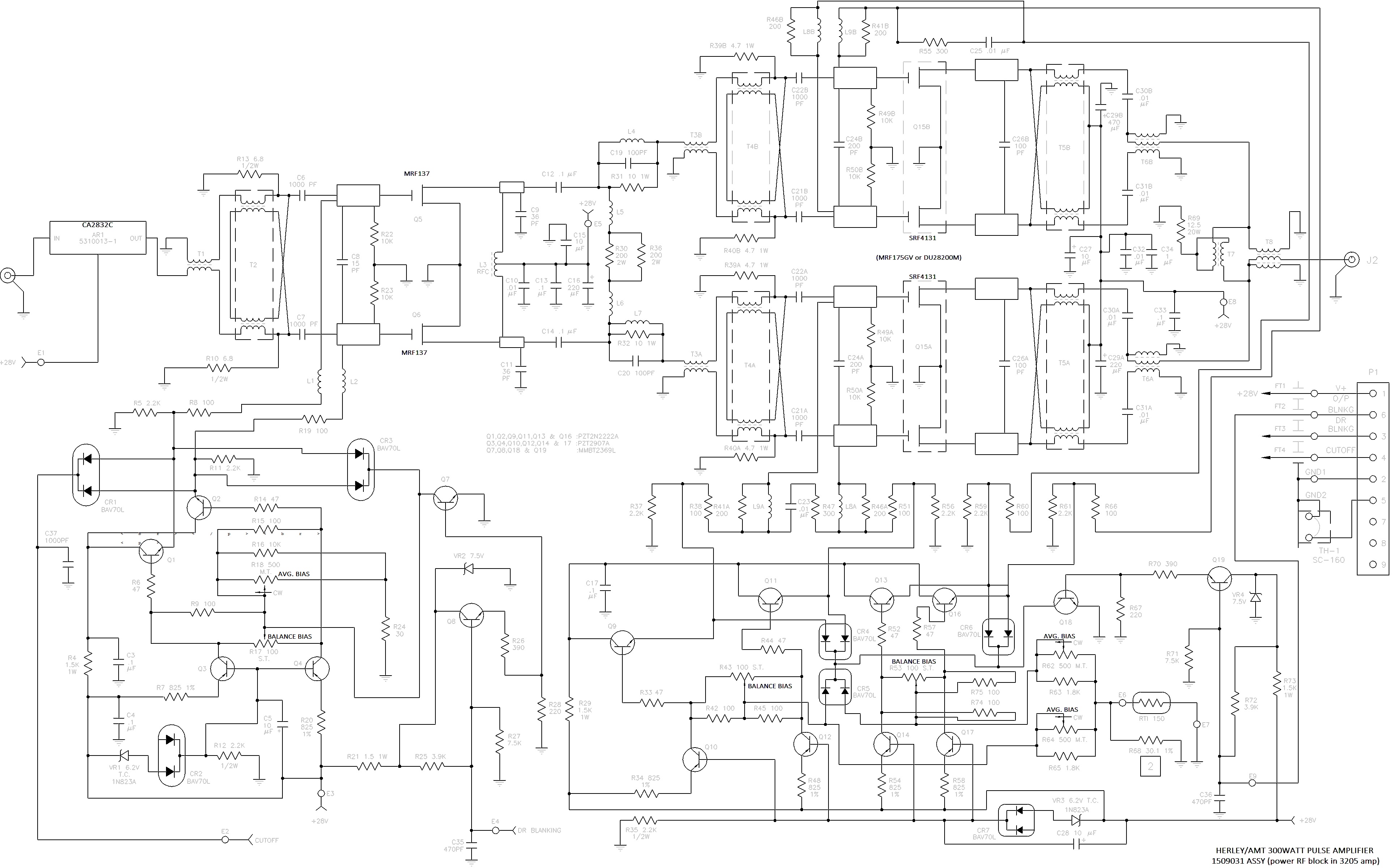
Symptom: distorted waveform for pulses higher than ~30watts, appears to be clipping, yet gain is OK (+59dB.)
All the power FETS test good, although the bias settings for the output stage are unusually low.
That's not the failure here.
The front end module's gain is wrong. This is a Motorola 1.6watt television cable amplifier block,
+35dB gain 5MHz to 200MHz. With the usual -4dBm input, the gain only measures +15dB (at 50MHz,
same at 100MHz.) One of the stages inside the module is probably fried. I've seen this problem
in two similar amplifiers from other manufacturers.
Older BASH schematics show MRF175GV as the output devices, while newer amps use a pair of DU28200M (Both available from MA-COM)
MRF175GV

DU28200M

SRF4131  - Found in AMT 3205 pulse amplifier (OEM marking, possibly is an MRF175GV matched pair?)
NOTES AND TRICKS:
The MRF175GV are dual MOS transistors, for operating in push-pull inv/non-inv mode.
Use scope clamp-on current probe and measure the current at the 28VDC input to the main amp. That
gives ability to adjust the DC bias pot for each transistor during unblank pulses. Add an extra
??1.3A??, as the bias voltage for each FET is brought up to 2.5-3.5v.
The main power-amp is splitting the input signal into an inv/non-inv pair, using a "magic-T" transformer; ferrite ring
wrapped with coax.
These give two identical current waveforms (one inverted,) fed to the gates of the two MRF137 FETs. The outputs aren't
sine (class AB distorted,) but distorted in exactly opposite form. Two more "magic-T" transformers split the two MRF175 outputs
to produce four
signals applied to the gates of MRF175GV pairs T3 and T4. The outputs of the four output-drive transistors are then
combined using two more 'magic-T' transformers (which also provide the +28VDC supply to the four.) One last much-larger
'magic-T' combines the two opposite-distorted signals to create a clean 120Vrms output sine at 300W into 50ohm.
The +28V supply to the main power amp is always drawing ~2amps (55 watt,) from the always-on driver transistors T1 and T2 (both MRF137.)
During the unblanking pulse, this load current rises to ~7.5amps (210 watts,) since the TC427 driver chips apply 2-3VDC to
the four gates of the output transistors. Each of four drain currents is around 1.3Amps, set by the four pots on the blanking board.
|
|
|
|
|
Department of Chemistry University of Washington Box 351700 Seattle, Washington, 98195-1700 Voice: (206)543-1610 FAX: (206)685-8665 |