BAD "ELBA ARTESYN" POWER SUPPLY
BLAX AMPLIFIER, BLARH, BRUKER NMR, MAGNETIC RESONANCE
Failed fan causes supply to fail
Bill Beaty (beaty atsign chem washington e d u)
Mon, 10 May 2004 16:07:47 -0700
Rather than paying the $1500 replacement cost, I've managed to repair a
bunch of these 28VDC power supplies in Bruker BLAX and BLARH amplifiers.
Want some info?
First note that these Artesyn or "Elba" 220VAC supplies WILL RUN ON 120VAC.
This makes testing easier. But I wouldn't recommend drawing a 200-watt
load when the line voltage is so low.
Also note that you need to place a small load on the +15v, -15v, +5v
supply outputs, and a 10-watt load on the +28V. If you run them with no load
at all, the switching-supply starts up, but then halts after a few seconds.
Without a load, the output voltages start out briefly correct, then start
dropping. So, load the +28V output with a 47-ohm 25w resistor. Put 91-ohm
2Watt on each of the + and - 15V, and a pair of 15-ohm 2W resistors paralleled
on the +5V line. If the load is too low, the supply voltage either doesn't
appear at all, or it rises to the wrong level, then the PWM chip shuts
down and the output decays slowly to zero.
On the first supply I repaired, the main bridge rectifier and the big
APT5025 FETs for the 365VDC Power Factor regulation were fried. These
components sit right on the 220VAC line, so any major line-spike can kill
them. The diode bridge is a weird thin little thing under the main PCB,
part number D20XB60, availible from Mouser Electronics, (600V 35amp bridge.)
The MOSFETs were APT5025BN from Advanced Power Technology, advancedpower.com/
http://www.dz98.com/wjj-pdf/apt5025.pdf
I found an actual APT5025BN, but probably a similar transistor would
work, if you can find a TO-247 package for 500V 23A 0.25ohm 300watt,
N-channel, gate threshold max 4v (such as IXFH24N50 or IRFP360
from DigiKey.)
The second dead unit also had a bad NPN transistor from ZETEX, which, if
I recall right, drove the gates of the main switching MOSFETS driving the
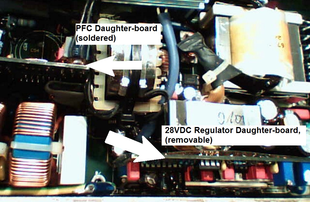
220AC to 365VDC switcher. The big MOSFETS were dead, as was the UC3854N
power-factor IC on the soldered-in PFC daughter board next to the 270uF 400V
capacitors. (See below for a schematic that's similar to the
daughter board PF-correction circuit.) There was a fried 22-ohm resistor
below the big ferrite transformer, and a shorted 1N6284A zener across the
28VDC output (located near the middle of three UC3524 chips near the
output terminals.) No doubt a surge on the 220VAC line shorted out one
component, and the large current destroyed everything else. Be sure to
check the value of that 22-ohm resistor, because if its value becomes far
more than 22 ohms, the regulated 28VDC output voltage can rise greatly.
A third unit had a stalled fan. The heat had killed the two big 270uF
400V electrolytics. Also, the values of tiny electrolytics were all wrong
on the soldered-in PF daughter board (the board next to the 270uF 400v
caps.) I found I could replace all these tiny capacitors without having
to unsolder the many pins of the daughter board. Be sure to mark the
polarity, since there's no silkscreen plus-signs on that PCB. These
capacitors are part of a tiny high-freq switching power supply that runs
components on that board, so high temperatures will bake out these capacitors
and make the supply fail during a power-up. (Apparently the Elba supply can
run almost forever when its fan is dead, but the extra heat slowly ruins
the capacitors critical for power-up sequence.) I replaced the two 47uF 50v
(a volt doubler) that runs the power factor chip, the 100uF 50V cap on the
corner next to the power transistor, and the two 22uF 35V caps next to
the fan connector (they're essential for the fan's power supply.)
Now our fourth dead unit was very interesting.
There is an apparent design weakness in the 30V section of the "Elba" power
supply used in some versions of the BLAX 300 and similar amps. When the supply
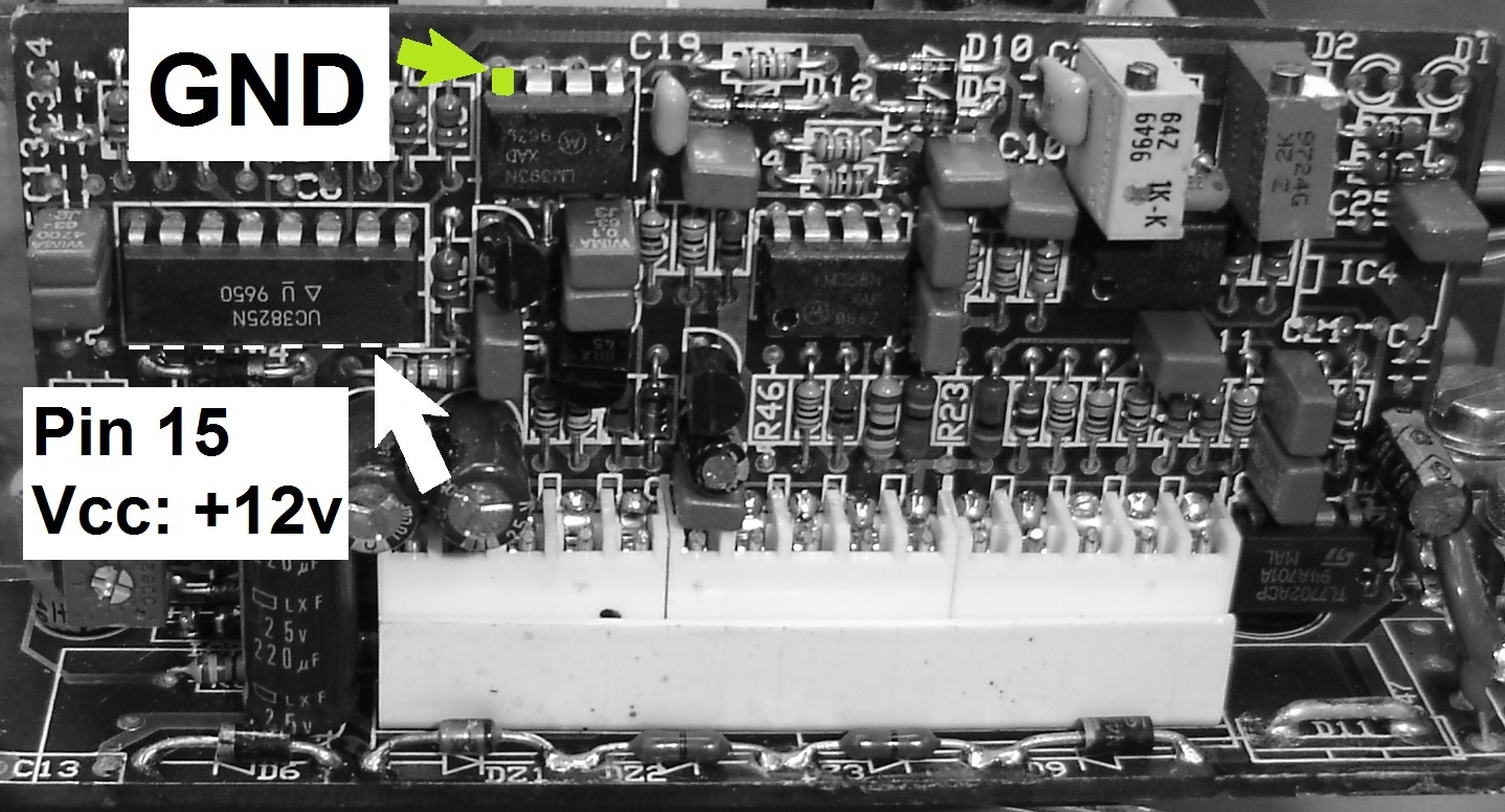
first comes up, the 30VDC switching regulator chip (UC3825) on the second
daughter board needs at least 9V to wake up and start making DC. In normal
operation it creates its own supply voltage from its own 30VDC regulated
output... it pulls itself into the sky by its own bootstraps! But during
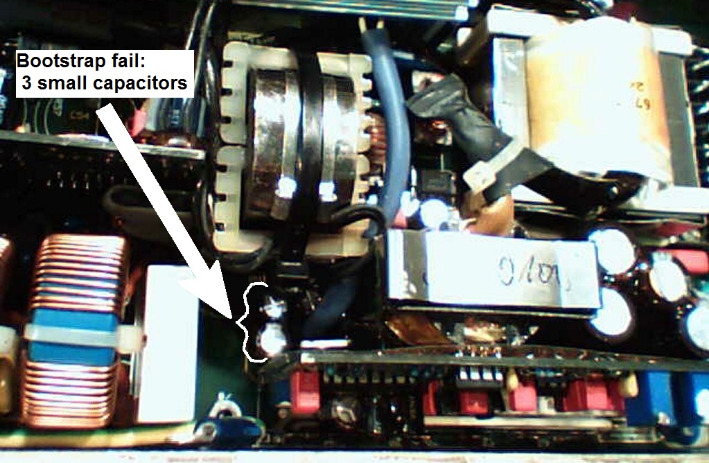
startup, it temporarily needs another supply. It gets this from a little
"bootstrap power supply winding" part of that big iron tapewound inductor in the
center of the PCB ...which is part of the power-factor switching circuit.
This winding's output is voltage-doubled with two diodes and three capacitors (two 10uF,
one 220uF, partly hidden under a transformer,) making 20VDC, which supplies a
LM7812 regulator, which supposedly puts out 12VDC for the UC3825 chip. But
the UC3825 draws 33mA, which can drag the 12v supply voltage of the bootstrap/
LM7812 down to 8.9V... and sometimes the UC3825 goes into continuous
repeating reset and never starts. It's waiting for its bootstrap-supply to
rise up above 9.0V. This all depends on temperature and on many component values.
This is possibly bad design? They should have given plenty of leeway (like
designing it to actually put out 12VDC, even when it draws 33mA as it does.)
Regarding the idea that heat can kill these supplies... yep, if any of the
three small electrolytic capacitors next to the LM7812 regulator in the voltage-
doubler bootstrap supply should get baked out, so their capacitance value
drops, or their internal leakage gets large... then these changes will
push things over the edge. The UC3825 on the removable daughter board at
the edge of the main board never gets its 12VDC, and the supply cannot wake
itself up anymore.
The usual symptom: your system was running for many days or weeks,
but then after being switched off, or after a building power failure,
it won't wake back up again.
(But sometimes, if you switch it off and back on more than once, it will
"catch," and start running.) Our dead supply had a 220uF 50V electrolytic
capacitor (next to the LM7812) which had changed itself to 20uF over the years.
When replaced, the supply worked fine again. But replace all three caps
in that cluster, The 220uF and the two 10uF, since they all are exposed to
high temp.
So note well that these Bruker amps often die after a power failure, but very
often THIS ISN'T CAUSED BY A SURGE. Instead, the power supply malfunctioned
weeks before, but the problem remained invisible as long as the amp remained
in operation. If the AC power should drop for a second or two, then the power
supply goes to sleep and will never wake up until the capacitors are replaced.
Also about ELBA power supply schematic:
I discovered that the schematic for the front end, the 220VAC input section,
is very similar to the schematic shown in the following app. note for the
UC3854 chip used in the supply's power-factor correction daughter-board.
It uses a big MOSFET and an inductor to massage any line input voltage (50VAC -
270VAC,) and it supplies 400 volts DC (365V) to the rest of the board. The
400Vdc is later switched as a 200KHz squarewave and applied to the ferrite
stepdown transformer to make 28VDC. Schematic:
Advanced Power Factor Correction Control ICs (n.b. schematic on page 4)
http://focus.ti.com/lit/an/slua177a/slua177a.pdf
Note that this power supply ***WILL RUN*** on 120vac, at least for testing.
Supposedly it up-converts any AC line voltage between approx. 60VAC and
250VAC. However, I wouldn't leave the whole NMR amp running on 120VAC,
since the supply is probably out of spec for power factor, and might
overheat during a 600Watts load.
Other schematics for your reference:
THE UC3823A,B AND UC3825A,B
ENHANCED GENERATION OF PWM CONTROLLERS
http://focus.ti.com/lit/an/slua125/slua125.pdf
UC3854 Controlled Power Factor Correction Circuit Design
http://focus.ti.com/lit/an/slua144/slua144.pdf
UC3854 provides power limiting with sinusoidal line current
http://focus.ti.com/lit/an/slua196a/slua196a.pdf
Optimizing UC3854 performance
http://focus.ti.com/lit/an/slua172/slua172.pdf
Also see messages (need password from AMMRL nmr forum ):
question about Bruker amps and their power supply modules
http://www.ammrl.org/archives/February-2004/13.html
question about Bruker amps and their power supply modules--Summary
http://www.ammrl.org/archives/February-2004/17.html
Bruker BLAX/H Power Supply Cooling Fan
http://www.ammrl.org/archives/June-2001/7.html
Bill Beaty (beaty atsign chem washington e d u)
Mon, 10 May 2004 16:07:47 -0700
More news!
The design weakness in the BLAX Elba power supply is NOT in the designed
capacitor values as I thought. But the problem is nearby: the LM7812
overheats the capacitors, causing them to slowly decrease in value over time,
so the supply fails early. There's a 10V Zener diode which seems to be the
origin of the problem, and it might help things if we change it to a smaller
value ( such as 4.3V 1N4731.) This is not essential. Instead just replace
the three bad capacitors to get things up and running again.)
The overheating of the three capacitors occurs because the little voltage
doubler on the big series inductor winding (the two diodes and three
capacitors, 220uF 10uF 10uF) is only supposed to supply its 22Vdc to the
LM7812 for a couple of seconds; during power-up until the main +30Vdc comes
on line. The output from this voltage doubler is passed through a diode, as
is the main 28Vdc output. Both are applied to the LM7812 regulator input pin,
and whichever is higher, that one powers the regulator. This lets the boot-
strap supply send current to the LM7812 during power up, then after a couple of
seconds the main +28V takes over from the volt-doubler when it later wakes up.
But unfortunately Elba has put a 10Vdc Zener diode in series with the 30Vdc
output to drop it down to 20V (no doubt because the LM7812 without
heat sink gets quite hot when given 30V input, so the series zener is
there to share some of the thermal wattage.)
So the little volt-doubler AND the main 30V are BOTH set to approx. 20V, and
if you happen to be unlucky and have just the wrong circuit values, then
BOTH ARE ALWAYS POWERING THE LM7812. Or perhaps the voltage doubler "wins"
and becomes the main supply for the UC3285 on that daughter board. This is
bad news for the three capacitors in the voltage doubler, since they normally
see two-ampere pulses at around 50KHz, and they will run fairly hot. Over
the months and years they get baked out, their values decrease, their 20Vdc
output voltage decreases, and finally the voltage falls below the 9.0Vdc
required by the UC3825 main 30Vdc regulator chip on the second daughter board.
It also doesn't help that the capacitors are right up against the very hot
LM7812 regulator; and that might even be the real trouble here after all. But
regardless, the temporary bootstrap power supply voltage gets too low, and the
system gets flakey during power-up and can't wake up every time. However, if
it's ALREADY running, the bootstrap supply is not critical for operation, and
the system will run fine... as long as you never turn it off!
:)
Or, if your BLAX or BLARH apparently dies right after a power-off, be aware
that in some cases the bootstrap supply is still VERY close to the correct
voltage. Try perhaps turning it off and on a couple of times (with luck
it may "catch" and start working.)
The cure we used (your milage may vary!): replace the two 10uF and the one
220uF capacitors (they're all glued together, positioned next to that
LM7812 voltage regulator approximately in the middle of the main board,
near one edge of the pluggable daughter board.) Replace them with low-ESR,
105degC electrolytic caps. But that doesn't fix the real problem. So also
look for a chain of resistors right at the edge of the main board (labeled
DZ1, DZ2, DZ3.) One is a 10V zener diode, the others are zero-ohm jumpers.
I replaced the 10V zener diode with a one-watt 4.3V zener. This lets the
poor little voltage-doubler circuit turn off when it's not needed. But
it makes the LM7812 regulator run even hotter than before during boot up.
If I see another one of these dead supplies, I think I'll also be putting
a couple of little bitty TO-220 heatsinks on the LM7812 regulator (HS214-ND
from digikey.)
See also (passworded):
Created and maintained by Bill Beaty.
|
