| Up to main | |||
Chemistry Electronics Services
|
|||
|
5415 Eppendorf Lab Centrifuge: randomly fails to power up. Power supply fail?
For non-chiller units, remove the four side screws, and the entire housing should come right off. If not, turn it upside down and note the rusty crust that's gluing the metal frame to the plastic! Slide a knife, or pry to break the bond. Then invert again, lift the housing carefully and reach inside to remove the ribbon cable from the PCB (pinch the plastic connector sides to release.) There are also two ground cables and the release-string to remove. (Also note, if you want to remove the main PCB, must unscrew the four screws on the BOTTOM of the centrifuge, not the four screws on the PCB itself.
I've now seen more than one Eppendorf lab centrifuge with the same problem: sudden death, as if a fuse has blown, but the fuses are fine.
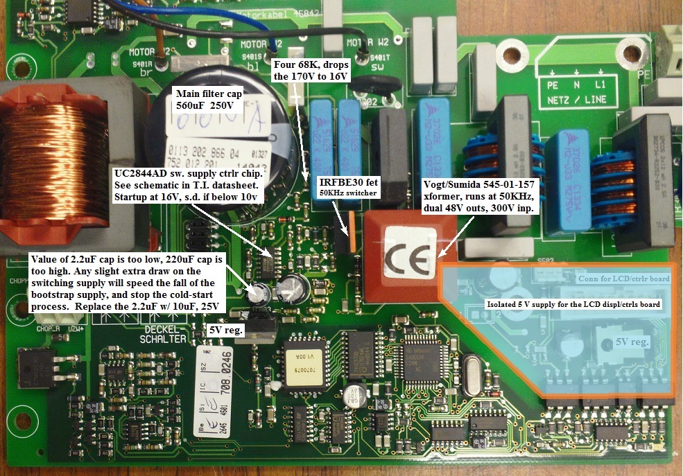
The LCD remains blank. Simple cure: increase a 2.2uF capacitor value to 10uF or higher (but stay below 100uF.) This fixes
an apparent problem of slow-aging of the "boot-circuit" in the main switching supply.
SEE ALSO:
photos on similar repair, 5417C Eppendorf Centrifuge
DETAILSIn both dead units the cause was the same: switching supply failure when the "bootstrap" startup circuit can't run the supply, but goes into constant resetting. If the supply could just start itself up once, everything else works fine. In the past with other systems, this failure comes from dead dried-out electrolytic capacitors. But replacing the large 2.2uF and 220uF caps in the centrifuge didn't help, and the values of the original components were OK.
The problem turns out to be ...possible bad design! Internal startup voltages are borderline, and any
small change will keep it from waking up when power is first applied. If I unplug the LCD ribbon cable
before turning on the main power, the switcher starts up OK, and the main 5VDC supply voltage
appears. The 5VDC supply for the ribbon conn. is found on that isolated LM7805 regulator, the one near the
rightmost edge of the pcb in the photo below.
Turn on AC power with ribbon plugged in and it fails, only rising to 2.4V, and the UC2844 supply-control chip goes
into constant restarting. But, but ...the LCD board is only a ~60mA load at 5V. A slight increase in a
1/3watt load shouldn't bring a power supply to it's knees!
Next I look at the circuitry around the UC2844 (which is live, lethal. Floating-at-170VDC-plus-120v). I use a (electrically
floating, dangerous!) scope to monitor the 16-volt input to the Vcc pin of the UC2844 controller chip. (This Vcc is
also found at the input pin of that other, non-isolated LM7805 regulator in the center of the board. The regulator tab
is also the chip's common.) A 2nd scope channel monitors the voltage generated by the high-freq transformer,
found at the cathode of a SMT diode next to the 220uF cap. During each restart, the 2.2uF cap must rise to 16V, then
the chip turns on, and the little VOGT 50KHz transformer should take over, charging up the adjacent, larger 220uF cap,
and power everything. On the scope, the 2.2uF does rise to 16V, turning
on the UC2844. That voltage now decreases rapidly, since the 2.2uF is acting as the entire power supply. The 50KHz
switcher runs for a moment, and it's output voltage (across the 220uF) rises rapidly. But before it has time to rise to 10V,
the voltage on the 2.2uF has fallen below 10V, and the UC2844 shuts down. Then repeat the whole sequence.
But, it just missed normal startup by
about half a volt! One cap voltage falls, the other rises, and they must pass each other in order to turn on
the supply. There's not enough millijoules in the 2.2uF to last for the whole millisecs needed to boot up the switching supply.
So, maybe there's a shorted turn in that VOGT high-freq transformer block. Or maybe the LCD front panel is now drawing
a few mA extra during the rising of the isolated 5V supply. Or maybe it was always supposed to be a 22uF
capacitor, not 2.2uF? The voltages and RC periods are very close to the edge of failure, and any little change
can push it over the threshold. Could I try replacing the little brown VOGT high-freq transformer? Nope, not
available. So, kludge it: swap the 2.2uF capacitor with 10uF 25V tantalum. Yep, that did it. Starts up now just fine.
(Hmm, in hindsight I probably should have used a 22uF or 47uF rather than a 10uF, just to keep the same failure from happening
again in a couple of years!) ANOTHER TRICK: stand up the capacitor on 1cm leads, then to keep it cool, bend it away from
the hot TO-220.
SEE ALSO: |
|||
|
Department of Chemistry University of Washington Box 351700 Seattle, Washington, 98195-1700 Voice: (206)543-1610 FAX: (206)685-8665 |