
| Up to main | ||
Chemistry Electronics Services
|
||
|
5417 C Eppendorf Lab Centrifuge: not working, LEDs blinking
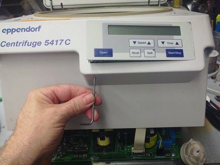
For the NON-CHILLER version, remove the four side screws, and the entire housing should come right off. If not, turn it upside down and note the rusty crust that's gluing the metal frame to the plastic! Slide a knife, or pry to break the bond. Then invert again, lift the housing carefully and reach inside to remove the ribbon cable from the PCB (pinch the plastic connector sides to release.) There are also two ground cables and the release-string to remove. (Also note, if you want to remove the main PCB, must unscrew the four screws on the BOTTOM of the centrifuge, not the four screws on the PCB itself.
I've now seen more than one 5417C Eppendorf lab centrifuge with the same problem: sudden death after
power had been turned off (or, it died right after a local power outage.) No fuses blown. The LCD remains blank.
Sometimes the LEDs for "OPEN" and "SOFT" start blinking rapidly. The +5VDC is missing, or giving crazy pulses
and never rising up to 5V.
The switching supply for the LCD assembly
is repeately restarting: a giant 2Hz sawtooth on the input to the +5VDC regulator. Simple cure: on the main PCB inside, replace a
tiny 22uF 35V capacitor labeled "C824," next to IC UC2844AD (switching supply controller chip.) This fixes an apparent
problem of slow-aging of the "boot circuit" in the switching supply. The 22uF has dried out and decreased below 5uF,
so during power-up, the DC supply cannot wake up before the boot-voltage decreases below 10V. (Yeah right, "simple" cure.
Only have to disassemble the entire unit to get to the bottom of the circuit board. SEE PHOTOS BELOW.)
 NEWER UNITS ONLY: PRY OUT THE LCD (with power off) 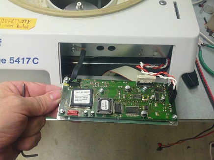 WITH POWER OFF, UNPLUG THE LCD, TURN ON POWER, THEN PLUG IT BACK IN. UNIT *MAY* START NORMALLY, BUT ONLY IF LEDS HAD BEEN BLINKING. 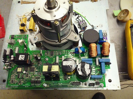 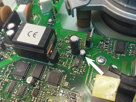 THE FAILED CAPACITOR. PERHAPS POSSIBLE TO SOLDER IN A NEW CAP IN PARALLEL, WITHOUT REMOVING THE DEAD ONE. SEE ALSO: |
||
|
Department of Chemistry University of Washington Box 351700 Seattle, Washington, 98195-1700 Voice: (206)543-1610 FAX: (206)685-8665 |