
| Up to main | |||
Chemistry Electronics Services
| |||
|
AXOPATCH CV-203BU HEADSTAGE
|
|||
|
The problem turned out to be a shorted thermistor. On the DB25 connector, find it at pins 7,18
(reading is below 40ohms, while a good headstage reads ~2K for room temperature.) The peltier
cooler is actually OK, just the temp-control feedback has failed. (Years later another one, same problem: thermistor says 620 ohms at room temp, should be 2.7K)
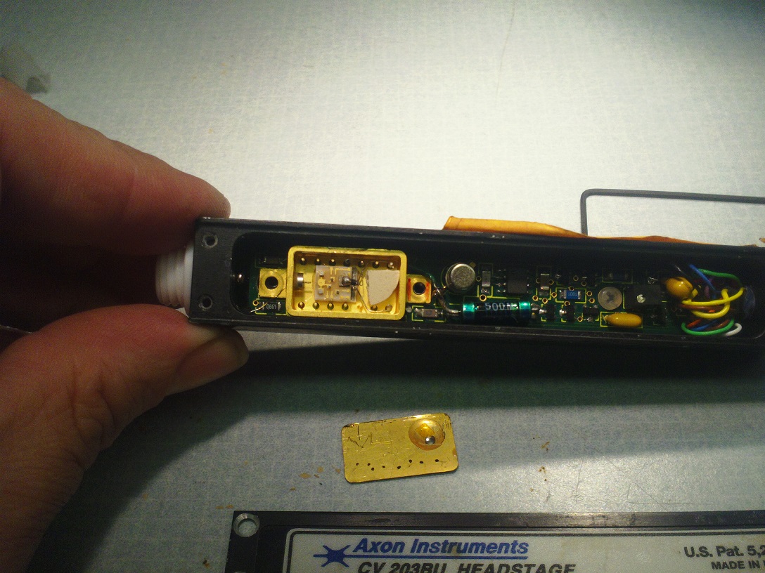
The thermistor is inside the front end module (gold shieldbox.) We found that it's possible to get
access by carefully slicing off the cover the box (glued with some sort of brittle epoxy.)
WARNING: EXPOSED SILICON AND DELICATE GOLD LEADBOND WIRES INSIDE! See photos below.
A close match for their thermistor is 2.2K NTC NCP18XW222E03RB, digi-key 490-12103-1-ND.
We used the smt 0603 version.
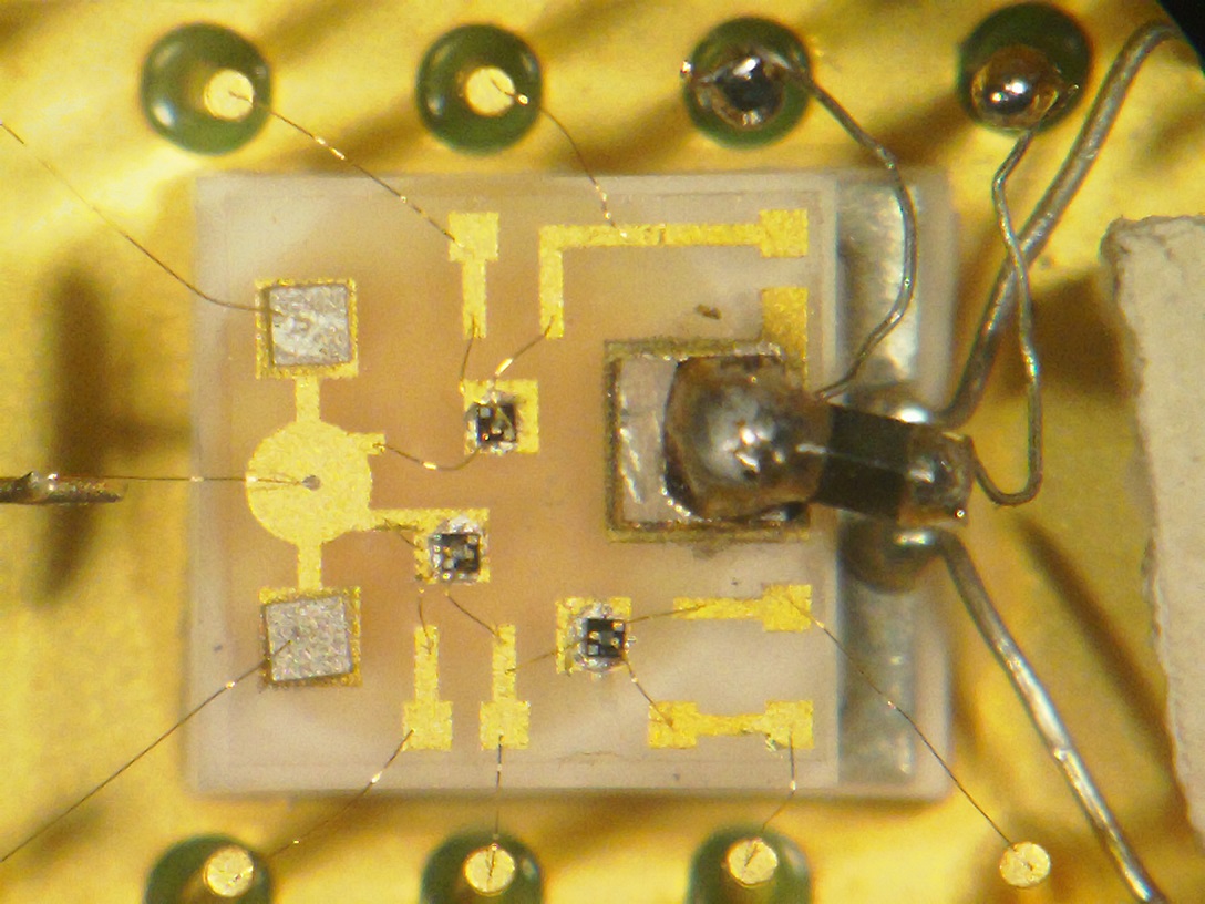
The front-end circuit is three discrete n-chan JFETS on a tiny ceramic PCB, plus one larger
thermistor, all connected to the DIP pins with *brittle* gold wires.
To repair: I removed the gold leadbonds for the dead thermistor, soldered our smt thermistor
to the top of the dead one, then used some #35 bare copper to connect it to the original pins.
(Find bare #35 wire inside fine-stranded rubber red/black test probe wire.) A large solder-blob gives low
thermal resistance, to avoid having the new thicker thermistor leads raising its temperature.
One problem: the clearance between the ceramic plate and the gold cover is very small, and
doesn't have room for a second thermistor standing upright atop the dead one. I soldered
our 0603 thermistor so it sticks out from the side of the solder-blob atop the dead
thermistor. This gave enough clearance.
Condensation from ambient humid air is an obvious issue. We don't have a vacuum-oven
for baking out and re-activating the dessicant pellet inside the gold shieldbox. The
gold shieldbox unplugs from a DIP socket. We'll
try removing the shieldbox and giving it an overnight 100C bakeout. Perhaps
flush with nitrogen while attaching the gold cover with epoxy.
|
AXOPATCH CV-203BU HEADSTAGE CABLE

	PCB	DB25
 BK	13	1	integrator feedb 1pF cap
 BR	14	2    (To pin DB-17) integrator feedb 4.7pF cap
 YL	15	7	Case GND common
 BK	16	14	+12.99VDC supply
 GN	2	8	integrator feedb 2.70K
 YL	3	17   To pin DB-2
 OR	4	4	? +11.78v  (main op amp outp)
 WH	5	19
 BR	6	15
 GY	7	6	-14.78VDC supply
 BU	8	18	RT2 thermistor 2.2K 10VDC (vs. pin 7)
 RD	9	3
 VI	10	16
 GN	11	11
 BU	12	5	driven gnd (guard)

 RD		24	Peltier + 4.3VDC
 BK		25	Peltier -


DB25 unused
9,10,12,13,20-23


---------------------

 14-pin Cooled Front-end Trans. Amp (gold shieldbox)

 pin    Probable function
 ---    -----------------

 1A -   Diff -Inp: "A" JFET Gate (To patch electrode)
 1  -   V High (+11.8V) to ?inp prot. diode?
 2  -   Diff Out: "A" JFET Drain
 3  -   Diff neg supply, A&B JFET Sources
 4  -   Diff Out: "B" JFET Drain
 5  -   Diff +Inp: "B" JFET Gate (To gold shieldbox)
 6  -   n.c.
 7  -   Peltier cooler +4.3V
 8  -   Peltier Cooler 0.0V
 9  -   n.c.
 10 -   On-chip thermistor 2.2K  (0.0V)
 11 -   On-chip thermistor 2.2K  (-9.98V)
 12 -   ?reset?  "C" JFET Gate (-6.56v)
 13 -   ?reset?  "C" JFET Source (+0.19V) (From DC amp via 500Meg)
 14 -   V Low ( to gnd via 5ohms) to ?inp prot. diode?
( The "C" JFET Drain connects to pin-1A, diff -Inp)