
| Up to main | |
Chemistry Electronics Services
| |
|
REPAIR HIGH VOLTAGE SHORTS IN CARY 6000 SPECTROMETER
[EARLIER SIMPLE FAILURE] burned molex connector, the ABS reading jumps around constantly. The visible source-lamp appears to glow, but actually it's flickering randomly because of arcing within the white molex connector on the main circuit board. Find this large, 6-pin connector at the left edge of main PCB. The incandescent lamp has two thick red wires to that connector, with brown/blackened plastic on those pins. Overheating has destroyed both the female and male sections, and even the solder joints beneath the male socket! The board connector is molex 5219 series, part 0015311066, and the cable end is 0019091069 (also need 0002095100 crimp contacts.) Yes, you must remove the entire PCB to unsolder the male connector. Take photos first!
Shorted HV failure. TWICE! Our UV/VIS/NIR spectrometer lost its -1KV high volt source. The
cause both times turned out to be an internal short on the PMT-control
circuit board. Both times this fault was easily found with a DVM: an unexpected
leakage path, well below 50Kohms, seen between the 1KV source and ground. The offending
PCB trace and the groundplane are both internal layers in the 4-layer circuit board
in the photo below. When I removed the 4-pin molex cable
connecting the main PCB to the PMT-control PCB, and powered up the instrument,
the -1KV at the main board reappeared again
(actually measured as -980VDC when working correctly.)
The shorted PCB with
the actual problem is positioned vertically all the way to the right of the instrument.
The actual -1KV switching supply is on another board: the large main board spread across
the top of the instrument, left rear.
Both boards have HV-protection covers: clear plastic sheets.
The HV cable connecting the two is the cable with the 4-pin Molex connectors, with one
pin having a heavy red HV conductor.
The PCB design unwisely routes a 1000vdc power supply trace
across an internal ground plane. Notice in the photo that the groundplane holdoff
does not surround the HV traces, it only surrounds the HV pins on components. Given
enough years, the HV slowly eats through the paper-thin epoxy-glass layer where
the HV traces cross the ground. Eventually it arcs
to ground, carbonizing a permanent path as it goes. Perhaps the same fault will
occur with many other units?
The cure is to cut traces free from the HV and replace it with a separate wire
to route the 1KV supply across the PCB.
But first you must use a Dremel tool to slice away the carbonized paths shorting
between the groundplane and the original 1KV trace that's found on an internal PCB
layer. We had one carbonized short appear at the spot where that trace led away from the
4-pin Molex. Later another carbon path arose at the via-hole near the "hot" end of the chain
of H11D1 optoisolators. While trying to find the internal short I also drilled out the
connection to the hot end of the orange disk capacitor, so used white RTV silicone
so that cap' would still be anchored mechanically by more than just its one remaining lead.
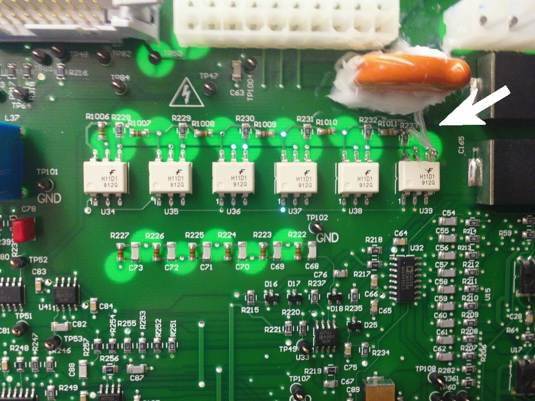
The white arrow shows the added wiring. Another added wire appears on the circuit
side of the PCB between the orange capacitor and the 4-pin molex seen just above
the white arrow.
Note that the chain of 200V optoisolators functions as a variable resistor (const. current source)
in series between the PMT and the 1KV supply. By varying the LED current to
the whole chain, the voltage drop through the chain can be varied, which subtracts
a variable voltage from the 1KV before applying it to the PMT detector.
|
|
|
Department of Chemistry University of Washington Box 351700 Seattle, Washington, 98195-1700 Voice: (206)543-1610 FAX: (206)685-8665 |
|