97355-61030 LTQ-lite LCQ LXQ, Thermo Finnigan
Analog Board catches fire! $20,000 damage
Our Thermo-Finnegan Ion-trap Mass Spectrometer, she no workee. On the K&M power supply MS1035 (also 3530?) the LEDs for +300 and -300 no longer light up. That's because it's now putting out ...SIX HUNDRED VOLTS?!
This is an old-age failure in the high-volt supply. But the failure will eventually apply max 800VDC to your large analog board, frying and charring various ICs. Our big analog board appears to be too damaged, but I'll attempt repairs. (We found a couple eBay take-outs, the first didn't work (gouges across pcb traces,) the second one seems OK.)
MEASURE THE +-300V ON YOUR MASS SPEC ANALOG BOARD RIGHT NOW! If your system is old, the 300V may already have started creeping upwards. The LEDs, the "good voltage" window detector, goes dark at above 310V. When it hits about 400VDC, everything starts smoking.
If the +-300V LEDs on your K&M high-volt supply box ever go dark, SHUT EVERYTHING DOWN IMMEDIATELY. The missing LEDs means that the 300VDC is aging, and slowly crept upwards, going past the upper LED window-threshold of 310VDC.
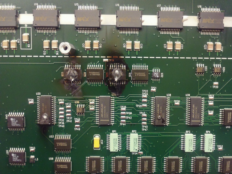
Our large analog board 97355-61030 has charred holes, several big op-amp ICs nearly burned in half! The culprit turns out to be the K&M supply, +-300 and +-150. The -300 supply is putting out -455, while the +300 supply is putting out +550VDC. (Later measurements were much higher! The damage is worsening. The LEDs are dark only because the output is outside the window of +-310V!) The huge voltage has created charred paths on pcbs inside the HV supply. And in several places on the large analog card, carbon-paths now connecting these doubled supply potentials directly to the analog-switch readback circuit on the large analog card (which expects 0 - 10.0V, not 550v.) Everything on the big analog board, within the 300V/150V "analog switch" readback amp section, is destroyed. One big voltage-regulator chip is blown in half, pcb charred.
The cause inside K&M supply seems to be tiny, progressively charred PCB paths in some cases, dried-out electrolytics in others. Bad electrolytics remove the (floating) 13VDC supply from the op amps in +300 switcher and the -300 switcher sections. When the op amps' 13VDC supply degrades below about 8V, the op-amp output hits the rails, breaking the feedback-loop, and then the regulated 300V output starts increasing, not decreasing! Bad flaw, not designed for the supply-volts to decrease during old-age failures. When fully failed (op-amp power supply gone, opto feedback gone,) the broken feedback loop now commands the 300VDC output to instead put out unregulated full 800VDC!! A bit of "UN-graceful degradation." UNDER CONST
Heres some of my old info.
The K and M supply MS1035 (also 3530?) is now sold by Spellman, X3530, often for several $1K, but sometimes
as low as $900. (I dont see any being sold currently.) Also search for Thermo Finnigan number 97055-98001
The supply is powered by 24VDC, with a tiny ten-amp picofuse. (I made a connector so I wouldnt have
to solder 24V cables. Digi-key WM3702 six-pin will fit, if you make a little notch in the plastic housing on the pcb.
CONNECTOR 24pin pinout
Top row, left to right:
- Ext case gnd
- Readback for +150v (0-10.0V ?)
- Com for +- 150 out
- Readback for -150V (0-10.0V ?)
- N.C.
- Main -150V out
- Com for +- 150 out
- Main +150V out
- N.C.
- N.C.
- Main -300V out
- Com for +- 300 out
2nd row
- Main +300V out
- N.C.
- Readback for +300v (0-10.0V ?)
- Com for +- 300 out
- Readback for -300v (0-10.0V ?)
- Board -enable (to LEDs on four optos.)
- Board +enable (to LEDs on four optos. +24V? )
- N.C.
- N.C.
- Com 24VDC pwr inp
- +24VDC pwr inp (has 10A fuse)
- N.C.?
On the optos ISO5 and ISO6, 7, 8, I see I had a shorting bar soldered between pins 4 and 5, to easily enable
one of the four sections
I recall (this was 3 years ago) that the 300V supply sections would turn off if not loaded. Or otherwise act crazy?
So, I ordered some few-watts resistors to connect to all four outputs, sized so each would draw a couple of watts at the
above-normal voltages. On the 300V lines they were 43K, three watts, soldered across the 300VDC which
appears at IR314B diodes, near the large rectangular orange 4.7uF capacitors.
Anything which screws up the feedback through the opto isolators and op-amp, makes the 300V go higher.
A very poor design philosophy!
The DC supply powering the LTC1800 op amp was way low, 7V not the designed 13V, but I dont remember
what caused that (might have been a partly-fried LTC1800 drawing excess current.)
Near the big orange 4.7uF 400V capacitors, I think I found very old charring under the big SMT resistors used
as voltage-dividers (voltage feedback sense? also the separate hi/lo voltage detector?,) black/brown stained pcb
underneath when unsoldered. Divider values were wrong because of surface carbon hidden under the resistors.
That MIGHT have been the original cause of the failures, but dont remember exactly. I put in new resistors,
standing up away from the scraped-off PCB, on short thick wires.
Away from the switcher section, on the output end of the main PCB, there was charring on traces under those two 2.2uF epoxy-dip through-hole capacitors on the 300V outputs, also charring under the big SMT resistors located between those two caps. Those resistors are dividing the +-300V and the +-150V, to provide a "readback" voltage, 0-9.9V if I recall. (Heh, the carbon-short had applied 600VDC to the CMOS analog switch on the big board. Burned it in half.)
The 8pin UCC3801DTR switching pmic controllers kept getting zapped during debugging, so I had to buy several from
digikey. Same with the LTC1800-I op amp, and the LM4040CYM five volt shunt regulator. The LM4040
is a SOT-23, marking code Y5C on the top. I see that I also bought a bunch of big shottky diodes B11000LB,
100V 1A, size SMB (at least one of those was bad, but might not have been an initial cause.)
The datasheet for UCC3801 (actually UCC2800 sheet) has a simplified product schematic for a HV
supply, somewhat similar to this circuitry, see fig 10-1, but without all the opto couplers of course.
ANALOG BOARD 97055-61030, BURNED ICs
|
Created and maintained by Bill Beaty.
|