Repair a J-Kem 280 (older type only, no USB port.)
TYPICAL FAILURES:
- Apparent leak, valve cannot shut off vacuum connection.
- With correct settings, the vacuum pump cycles on and off too rapidly.
- Pressure display flashing: "inP+ FAiL" (or, pressure is wrong.)
- Pressure stays high, pump is OK, but valve sticks closed (especially if warmed up.)
|
|
- 1. Vac leak
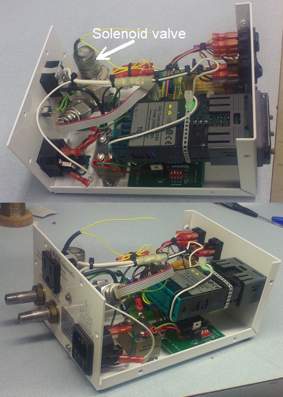
- If not an external leak somewhere, then inside the unit, debris particles/buildup is keeping the solenoid-valve's tiny teflon disk from
sealing on the polished steel. Inside the case, the solenoid-valve is the large silver cylinder-assembly in the
vacuum line. Mark the orientation of the upper coil, then remove the four
allen screws (3/32") and the coil section. (don't lose the four tiny lockrings!) Clean any visible build-up
from the steel parts, and from the teflon disk on moving iron core. Don't dislodge the tiny disk. DON'T CLEAN WITH
COMPRESSED AIR, you might damage the silicon-membrane pressure transducer.
- 2. Pump has too-fast on/off cycling
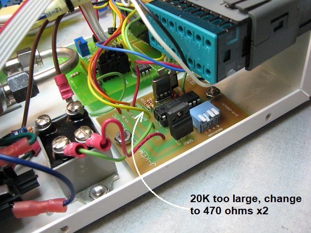
- I've seen a defect on some of these. Too much EMI noise-pulses on PIC processor pin-17 and pin-18,
those pins detecting the relay-contact output from the pressure controller. The noise from the 120V line is fooling
the PIC when the pump-relay contacts are open/floating. Just add stronger pulldown
resistors for pins 17 and 18. On the pcb for the PIC, (located under the digital display/control module,) solder one
470-ohm resistor across each of two existing resistors (resistors near the PIC's
crystal, labeled 20K.)
- 3. Error on display, the LEDs read "inP+ FAiL" Input fail, (or otherwise the displayed reading is completely wrong.)
- Vacuum transducer was damaged by corrosion or over-pressure. Or crushed when someone
accidentally rotated the entire plumbing assembly into the enclosure cover! Replace with a
near-identical version, 6-wire piezoresistive gauge, part number is TE-connectivity/Meas-specialties
85-015A (85-015A-4C is exact part, others need plumbing adapters 1/4NPT to 1/8NPT etc.) One from
DigiKey is 223-1452-5-ND about $80. This is
"Measurement Specialties" model-85, 15psi, Absolute, 1/4NPT, cable w/conn.
(Or of none available, try 85-015G for gage-pressure rather than absolute.)
After replacing the sensor, I found that the "span" trimpot needed no adjustment, but the zero pot was off a bit.
As the J-Kem manual says: set the switch to "full vacuum," then pump down to well below 1-torr
(tested with another gauge.) Warm up for 10min, then set the "ZERO" trimmer for zero displayed pressure.
See also
transducer 85-015A PDF datasheet
- 4. Valve sticks closed, no vacuum (especially when warmed up.)
-
Your pump runs, but the pressure reading doesn't fall, even when switched to "full."
Pump tests as OK, but pump-down doesn't happen, since the internal valve on the J-Kem doesn't open.
NEW ISSUE: I've now seen failures where the 470uF filter cap on the 24Vdc line is too old, cannot sufficiently "kick" the solenoid with 25Vdc (then falls to 19.5V.) 470 measured good, but ESR of many ohms, so it had dried out. Solder another new cap across the two pins of the adjacent 4pin bridge rectifer. COMMON ISSUES:
Sometimes (rarely) the solenoid's teflon valve does stick because of adhesive contamination, therefore simply open it up and clean it as per #1 above. But instead in many cases, the valve itself is not
actually sticking. Instead the field is too weak because the current drops significantly when the coil is warm
(140-ohm resistance rises to 175 ohms,) and now the valve won't open unless the drive -voltage
is higher than 24VDC. Time for a replacement coil? Quick fix: add a couple of
pipe-clamps to the coil-case, as heat sinks. Seems to cure the slightly-flaky valves.
Better: add a wired-in low-watts hold circuit: 150ohm 2W resistor in series with the +24VDC
supply to the valve, then a 2200uF 35V capacitor across that resistor. This cools
the coil by reducing the longterm coil power to 1 watt, but then with a 4watt start-pulse.
( Note that, after this modification, any unusual rapid half-sec on/off cycles may
keep the capacitor from entirely resetting (discharging,) which would make your
orignal problem worse! )
|
|
Typical voltages on LM324 op-amp pins ~760torr
|
pin-1 +5.20v |
|
pin-14 3.09v |
|
pin-2 +2.48v |
|
pin-13 +3.80v |
|
pin-3 +2.48v |
|
pin-12 +3.80v |
|
pin-4 +12.1v |
|
pin-11 -5.1v |
|
pin-5 +2.29 |
|
pin-10 +3.86v |
|
pin-6 +2.29 |
|
pin-9 +3.86v |
|
pin-7 +1.50 |
|
pin-8 +4.57v |
Pin 4,11 is the bipolar power supply +12, -5
Pin 10,12 is the transducer diff signal (about 50mV at 1atm)
Pin 1,2 is the .78mA supply to the floating transducer bridge
Pin 14,8 is the amplified diff signal 1.5V
Pin 7 is the output, the 0V - 1.5V pressure signal
Circuit description
See: PARTIAL SCHEM
The front end schematic is a near match to the one shown on the
transducer spec sheet, a 3-section
instrumentation amplifier using six 100K resistors (SIP packages) and one "Rgain" resistor.
The first op-amp segment of LM324 (pins 1,2,3,) along with the LM336 2.38V reference-chip
and the SPAN trimmer, together form a constant-current generator sourcing about
0.78mA to the transducer-bridge input (to transducer pin-2, pin-3.) Since
the transducer diff-out is zero during vacuum, this constant-current value determines
the transducer's 1atm, 760torr diff-output voltage. The LM324's pin-1 output voltage (around +5V to +6V) goes
to transducer bridge input pin-3, and LM324's input pin-2 is the 2.38V reference voltage going to transducer
bridge input pin-2.
The pressure transducer provides a floating "gain settting resistor" on its pins 5,6.
The remaining three op-amp segments of the LM324 are wired as an instrumentation amplifier,
with the amps Rgain resistor being the transducer's floating resistor. That's
the reason for the transducer having six wires rather than the expected four
for a bridge. (I measured one of these Rgain transducer resistors to be 8.485K ohms, another 8.468K)
At less than 1-torr vacuum, the transducer's balanced-bridge puts out 0V diff. signal,
with its pins 1,4 both having a voltage at the average of pins 2,3 voltages to ground:
(5.2v + 2.38v )/2 = 3.8v on xducer pins 1,4
At ambient pressure 760torr, the balanced-bridge transducer's output pins give roughly 50mV diff-signal,
(roughly half the spec sheet value of 100mV,) amplified by op-amps to about +1.5V on LM324 pin-7,
which is (as expected) roughly half the 3.012V spec sheet value for an instrumentation amp.
J-Kem sets the mA supply on pins 1,4 to half the recommended 1.5mA input to the transducer bridge.
The +1.5V signal is then divided down by 100x (100K, 1K) resistors and applied to the Thermocouple
input of the jkem3300 gauge.
Zero-adjust is a 10K pot across +1V, -5V. The pot's slider is then divided down by 100K, 3.9K resistors and applied (through 100K) to LM324 pin-5. (For a very rough zero setting, just unplug the 6-pin transducer, and adjust that pot for zero on the front display.)
The solenoid drive is via the 3300 CAL controller's relay output, getting the +25VDC from the pcb, via the front DPDT switch. Note that this supply voltage drops to 19.5V under load, when the solenoid is drawing its typical 140mA.
Other Misc. Info
External vacuum connections are USA type 1/8 NPT pipe thread.
Ground is case, also found at the 1st pin of LM385, and the bare TO-220 tab of LM78M12 regulator.
Power supply is a 24vac transformer with two secondaries, two bridges and filters. Verify +25VDCat LM78M12 regulator pin-1 and +12Vdc at pin-3,
and -5Vdc on soldered bare jumper running between LM324 and the 6pin transducer conn on the pcb.
Verify 2.48Vdc reference on LM324 pin-2 or pin-3.
100watt SSR relay is Schneider (Magnecraft) 140VAC 25A w/3-32 vdc inp, 70S2-03-B-25-S, plus a 1A slo fuse on the power inlet connector.
Rough calibrate: set the SPAN pot to halfway (250ohms,) later adjusted to produce around +5V at pin-1
of op amp LM324 when the vac. transducer
is present, at 1ATM. This drives the transducer at about half its rated current, 0.75mA. At 1ATM ambient pressure,
there should be about +1.5V to gnd on LM324 pin 7, and also a diff. signal of about 1.5Vdc measured
between LM324 pin-8 and pin-14. Perform crude zeroing by unplugging the sensor and setting the ZERO pot
to give a pressure display of zero torr.
LINKS
