CATEGORIES
MaSCOT IRD Final Report
Final report for APL Science and Engineering Group (SEG) 2016 Internal R&D Project “Underwater Stereo Cameras for 3D Reconstruction”
Summary
This project supported the development of MaSCOT, a shallow-water stereo camera which allows the collection of greater-than-HD stereo video imagery. It also supported the development of a set of software tools for recording, processing, and calibrating this video imagery, as well as tools for the realtime production of 3D point clouds from video streams. MaSCOT necessitated system-level electrical, mechanical and software design to accommodate the choice of stereo camera sensor and the computational needs of the reconstruction software.
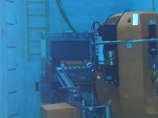
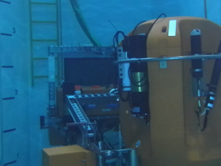
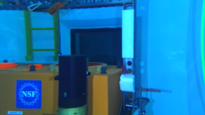 Sample left and right images of the Shallow Profiler at 1920x1080 (click for full-sized images
This project achieved the primary goal of developing a functional in situ stereo imaging system capable of shallow water operation. The system has been used to collect a number of reference data sets of targets of interest at a variety of resolutions (as above), and to perform intrinsic calibration of the camera head, despite difficulties achieving a converged calibration solution using the distortion model inherent in the camera support software.
The selected real-time 3D reconstruction software (LSD-SLAM) was also demonstrated operating over a set of test images, including monocular video from MaSCOT. However, collection issues with the initial test data sets reduced the suitability of this video for 3D reconstruction. There was insufficient time within the project to complete the integration of stereo-generated 3D imagery into the real-time reconstruction algorithm.
On the basis of data gathered within this project, a revision of the stereo camera system has been developed with greater lighting capacity to reduce video artifacts (e.g. blurring, color aberrations) seen in the collected test imagery. This revised system is functional pending collection of revised test video in the OSB test tank.
Introduction
The original IR&D proposal was to develop a technology demonstrator within APL Ocean Engineering for collecting stereo video imagery in shallow water (OSB test tank, R/V Henderson), for recording that data in situ, and for processing that data to produce 3D reconstructions – in post processing with a growth path to realtime operation.
The original proposal described two stereo cameras: the StereoLabs Zed and a multi-camera Elphel configuration (Elphel shown below). Low-cost underwater enclosures would be built for both, and both would be used to capture representative test data in the tank.
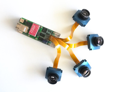
This effort also supported development of tools for recording data with the two systems and calibrating the respective cameras. It also supported in-depth study and adaptation of an existing Simultaneous Localization and Mapping (SLAM) algorithm drawn from the recent Open Source SLAM literature.[1]
Variations from Proposed Effort
It quickly became evident that splitting effort between two camera systems was not practical and would result in an incomplete effort with both cameras. Given the experimental status of the Elphel cameras and the potential computational power associated with the Jetson mainboard selected to support the Zed, the the Zed-based solution was selected as the primary development focus.
Design
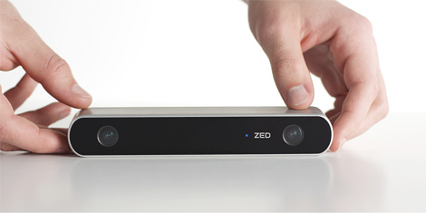
The Stereolab Zed stereo camera (above) is a hardware-software solution consisting of the two-camera Zed USB3 camera head itself and a companion video processing library which uses NVIDIA CUDA GPU acceleration for performing dense stereo matching and depth estimation. These two hardware constraints (USB3 and GPU) drive the system design.
The simplest solution would place just the camera in a waterproof enclosure, and route its USB3 signal (including both data and power) to the surface. USB3 offers data rates up to 5Gbit/sec (greater than Gigabit ethernet) over relatively short distances. Experience with passing its high-rate differential signal through e.g. wet connectors or conversion to other modalities is limited. A COTS solution exists for translation onto fiber optics for long-distance (300m+) transmission,[2] however the cost and complexity of hybrid EO wet connectors is outside the scope for this project.
As an alternative, a USB3-enabled host PC could be co-located with the camera in the pressure housing. This offers multiple benefits: it most closely resembles the standard Zed configuration with the camera connected directly to a host PC over USB3, reducing technical risk; the PC can convert the Zed format locally for e.g. local storage or transmission over better-tested interface like Gigabit Ethernet; and provides local control and logging for additional sensors. The requirement for an NVIDIA GPU inherently limits the options to either a conventional PC with graphics card (e.g. PC/104+, etc) or the solution chosen in this case, the NVidia Jetson TX1 singleboard development kit:
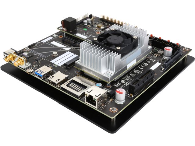
The Jetson TX1 comes in a low-cost development kit consisting of a processor mainboard containing a quad-core ARM64 processor and a 256-core NVIDIA GPU, and a development motherboard containing a number of common peripheral interfaces, including USB3, Gigabit Ethernet, RS-232 and SATA. The design intention is that the dev. kit allows rapid prototyping with the Jetson platform, driving the subsequent design of an application-specific host board containing only the necessary peripherals. To keep costs low and minimize technical risk, we did not design a custom motherboard. As such, the large size (9.5" x 9.5") of the standard motherboard drives the final enclosure size. In the interim, a number of aftermarket motherboards have become available[3], and future revisions of MaSCOT could be significantly smaller.
NVIDIA provides a Linux-based board support package for the Jetson TX1 (Jetpack), which automatically configures the board with a Linux kernel and filesystem, and a number of CUDA-accelerated libraries. The Stereolabs API supports the Jetson TX1 directly, making the initial bring-up of the Jetson TX1 - Zed Camera pairing relatively pain-free. As it is Linux+CUDA based, this also makes the software environment on the Jetson functionally identical to a Linux desktop, allowing the majority of algorithmic development on the Jetson to work without change on an Intel desktop (and vice versa).
Architecturally, MaSCOT is very simple. At its core is the Jetson TX1 mainboard. It drives the Zed camera over USB3 and an 512GB SSD over SATA. Both of these interfaces draw power from the Jetson itself. The Jetson connects to the outside world over Gigabit Ethernet.
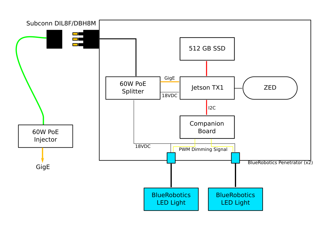
Enclosure, power, lights and cabling
Prior to the MaSCOT project, the lab had purchased a number of submersible IP cameras which connected to the surface through an 8-pin Subconn DBH8M Gigabit ethernet connector. These cameras used 802.3af Power over Ethernet (PoE) to provide both power and network over an 8-conductor (4 twisted pair) Falmat Xtreme Net cable. On the surface these cables terminated in a single RJ45 connector, requiring a COTS PoE switch to power to the cameras.
For cost efficiency, the MaSCOT design reused the existing cables from those cameras, using the same 8-conductor Gigabit ethernet cabling and DBH8M penetrator. For lighting, two BlueRobotics 1500 Lumen LED lights were selected. This gave a total system power budget of approx 45 W (15W per light and conservatively 15W for Jetson+Zed+SSD). Unfortunately, conventional PoE+ offers only 25.5 W of power.
We circumvented this issue by using a non-standard “Ultra PoE” injector and splitter designed for 60W. These units performed flawlessly, offering the requisite power to the unit. The selected splitter included DC regulation to 18VDC, allowing both the lights and the Jetson to share a single DC bus without further power conditioning. Overall power efficiency was not a core concern other than staying within the PoE power budget and minimizing waste heat within the enclosure.
The enclosure was then designed for ease (and cost) of manufacturing. The main body is machined from a single block of Delrin. A transparent polycarbonate endcap is installed on one end, and an aluminum endcap is installed on the other, providing a thermal path from inside the enclosure to the water. The endcap has three penetrations: the DBH8M ethernet connector and two peneratrators for the BlueRobotic lights. The BlueRobotics lights could have been daisy-chained to use a single penetrator, at the cost of losing independent dimming control on each light.
Companion Board
During initial testing it was discovered that the Jetson board does not turn on when power is applied — instead a physical button on the motherboard must be pressed. Further investigation showed there was no convenient (software) workaround for this shortcoming. Clearly, this would not work once the Jetson was fully enclosed.
This issue was circumvented by designing a breakout circuit board which contained a TI MSP430FR2311 microcontroller. This provided a convenient platform for a number of subsidiary system functions not otherwise provided by the Jetson mainboard:
- Initiate Jetson power-on when power is applied
- Watchdog and remote power-off or reset
- Break out Jetson expansion ports (console, RS-232, I2C, etc)
- Host a subsidiary air pressure/temp sensor
- Provide the PWM dimming signal for BlueRobotics lights
- Out-of-band communications over RF
The MSP430 controls the power and reset buttons for the Jetson, and generates a PWM dimming signal for the LED lights. The Jetson communicates with both the MSP430 and Bosch pressure/temperature sensor over the I2C bus. Common I2C tools within Linux provide a reasonably straightforward mechanism for communicating with the MSP430. A process on the Jetson communicates with the MSP and pressure/temperature sensor, logging pressure and temperature data to disk.
The MSP430 is designed to provide a watchdog functionality but to reduce the potential for error, this functionality was disabled — better to just power cycle the whole system as needed during initial testing.
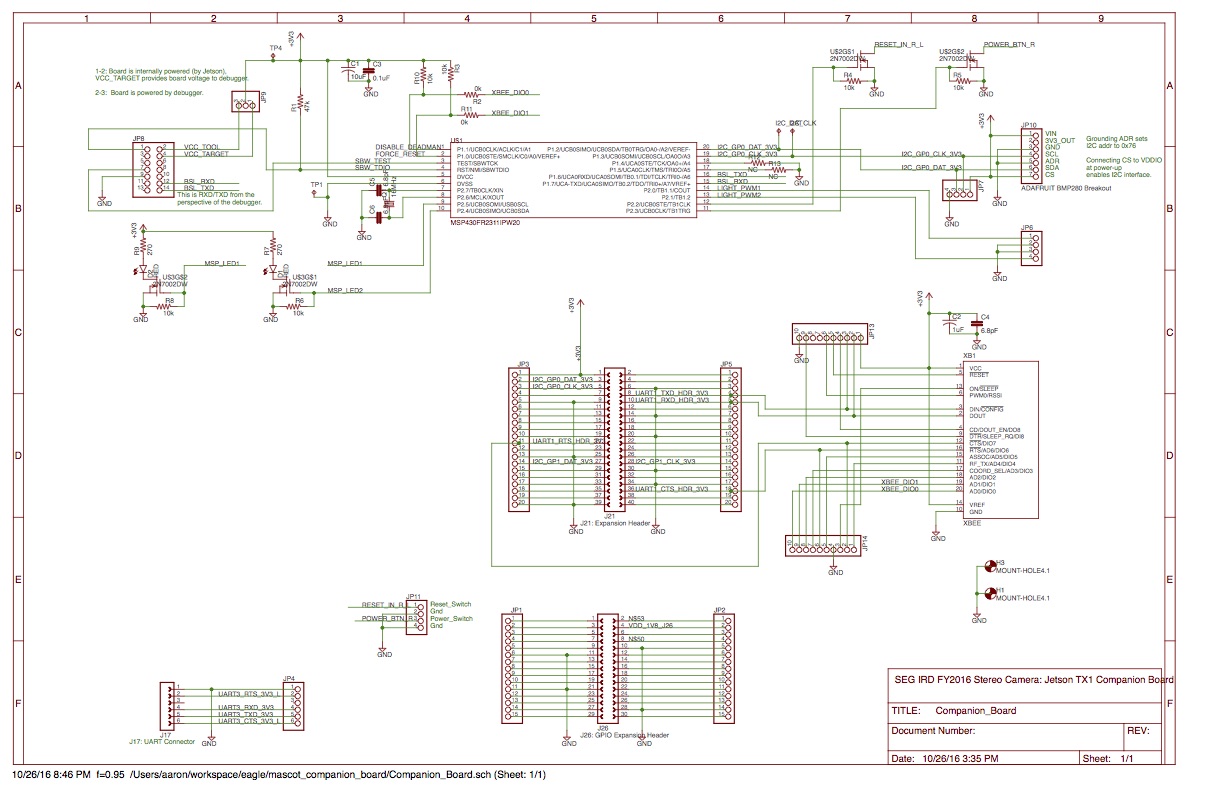 MaSCOT Companion Board Schematic. Click for PDF
Due to the limited pinout in the existing 8-pin cables, there was no support for a hardwired out-of-band connection to the Jetson if the ethernet interface failed to come up. The companion board hosts a Digi XBee 2.4GHz data radio which is directly connected to the Jetson serial console. This provides emergency out-of-band access to the Jetson when the unit is not submerged.
Software
Two software components were developed as part of this project.
-
The Zed library package comes with a set of powerful recording and visualization tools but these tools are all GUI-based. Given the limited bandwidth available over the gigabit ethernet, the GUI functionality was extremely limited. Using the Stereolabs-provided API, a series of tools were written which allowed console-based recording and playback of the Stereolabs-proprietary SVO format. This also provided direct experience with the Stereolabs API which was deemed essential for long-term integration of the camera into any perception software.
-
The second software goal was to develop a close working relationship with an existing Simultaneous Localization and Mapping (SLAM) software package. SLAM research has exploded over the last decade, resulting in a plethora of capable platforms whose designs have been driven by the practical and pedagogical needs of their creators, resulting in a constellation of more-or-less robust, more-or-less capable tools in varying states of maturity and disrepair. Against this landscape it seems irresponsible to create a new toolkit from scratch. Rather it seemed appropriate to choose a well-architected, functional toolkit and adopt/adapt it for further use.
After evaluating a number of options, the LSD-SLAM[4] toolkit written by Jakob Engels at TU Munich was selected for initial experimentation. It appears to have good performance over relatively large visual data sets, is available under an Open Source license, and is well architected. Importantly, it is designed for multi-threaded CPU-only operation (including the use of x86 and ARM SIMD instructions when available), leaving the GPU available for the Stereolabs toolkit, and/or for other image-processing acceleration.
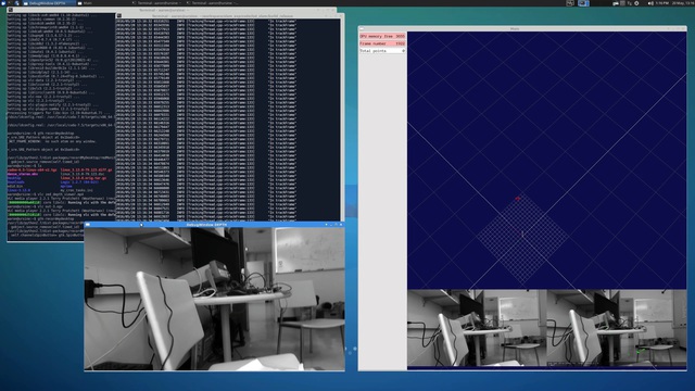
The project supported a familiarization period with LSD-SLAM including a significant rewrite of its threading code for clarity and resolving a number of obscure dependencies. The code was also extended to make use of stereo imagery and the depth models generated by the Zed (it should be noted the Dr. Engels has published separately on performing stereo matching within LSD-SLAM [5] but has not made that code publicly available). The LSD-SLAM software was shown working on data sets captured by the Zed and other cameras at APL, although it remained sensitive to the quality of the input video, as discussed below. Critically, the development process provided the familiarity for future extension and development of the core LSD-SLAM platform.
Screenshot of LSD-SLAM (right window) running on MaSCOT video captured in Henderson Hall. (click image for larger version)
Testing
The MaSCOT prototype was completed in June 2016. It was immediately deployed in the OSB test tank to coincide with qualification testing of the Cabled Array Shallow Profilers in advance of the 2016 Cabled Array Operations and Maintenance Cruise.
In total, approximately 30 minutes of in-water stereo footage was collected at VGA (640x480) and HD (1920x1080) resolutions. The camera collected both imagery of the Shallow Profiler:
Sample left and right images of the Shallow Profiler at 640x480 (click for full-sized images
Sample left and right images of the Shallow Profiler at 1920x1080 (click for full-sized images
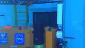
and imagery of a fiducial-based calibration target:
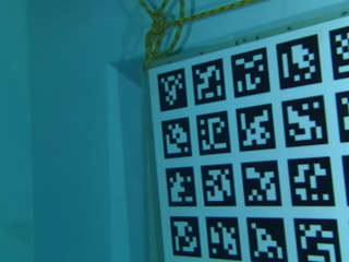
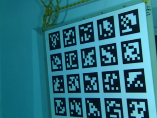
Sample left and right images of calibration target (640x480)
Results
Camera calibration
The immediate goal was to estimate the camera calibration (intrinsic properties and distortions) for the individual left and right Zed cameras at the two sample resolutions (VGA and HD1080).
Camera calibration is essential for accurate reconstruction. The Zed is shipped from Stereolabs with a known calibration (in air) using a reduced-order (4 coefficient) version of the well-documented radial distortion algorithm also found in e.g., OpenCV. The Stereolabs library is initialized with this factory calibration but also implements an adaptive self-calibration which uses an undocumented (proprietary?) algorithm to improve calibration accuracy over time. Adapting the Zed to underwater operation requires substituting an in-water calibration for the factory calibration. The impact of the self-calibration routine is not known, although it can be disabled at runtime.
The extrinsic (stereo) calibration for the unit should not be affected by operating underwater, as it represents the physical arrangement of the two cameras.
Calibration was performed using a calibration target based on the AprilTags fiducial (as shown in the images above). The calibration itself was performed using an internally developed calibration library based on the Ceres optimization package. This package supports a number of calibration models, including the radial model used in OpenCV/Stereolabs and the angular model of Kannala and Brandt.
As detailed in [A], calibration using the radial model was highly unstable for both cameras at both resolutions, while the angular model was stable in all cases. Unfortunately, the calibration model in the Stereolabs library is fixed and the closed-source library cannot be extended with an additional distortion model. Two alternatives were considered:
-
Using the angular distortion model to explicitly undistort incoming images, then provide the Stereolabs library with those undistorted images. Unfortunately this would require interceding in the flow of images from the camera to the library, which is not supported – there is no way to to introduce images into the Stereolabs dense depth mapping algorithm except directly from the Zed or from their proprietary SVO files format.
-
Develop a set of radial coefficients which approximate the angular distortions over the extent of each image. If $$\mathbf{a}( X,Y,Z ; a)$$ is the angular distortion function which maps a world point $$(X,Y,Z)$$ to image point given angular coefficients $$a$$, and $$\mathbf{r}( X,Y,Z ; r)$$ is the similar radial distortion function for radial coefficients $$r$$, then the approximate radial coefficients $$\hat{r}$$ can be found by
$$ \DeclareMathOperator*{\argmin}{arg,min} \hat{r} = \argmin_{r} \sum_{x \in (X/Z), y \in (Y/Z) } | \mathbf{a}(x,y ; a) - \mathbf{r}(x,y ; r) |^2 $$
Due to the formulation of both distortion functions, the ratios $$X/Z$$ and $$Y/Z$$ can be used in lieu of an independent $$Z$$ variable. The range of $$(X/Z)$$ and $$(Y/Z)$$ values visible in the image can be estimated by undistorting the four image corners.
These approximate radial distortion coefficients can then be provided to the Stereolabs library, which will then use those coefficients to undistort incoming imagery. Details on this process are given in [A].
Reconstruction
The second goal was reconstruction from the underwater imagery (once properly undistorted) using the LSD-SLAM software. The recorded imagery from the OSB testing was fed into the modified version of LSD-SLAM as both monocular imagery, and the software was able to start a 3D reconstruction. Unfortunately, this ingestion process revealed a number of photometric weaknesses of the captured data: an inconsistent frame rate, frequent video “glitches” and large jumps between subsequent frames.
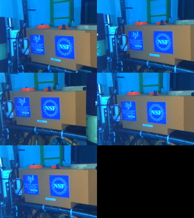
The strong jump to the left is due to one or more missed frames in the MaSCOT recording. A black frame is shown whenever the GIF resets.
These relatively large jumps resulted in periods of sequential images with relatively low overlap, causing the visual odometry component of LSD-SLAM to lose its tracking. LSD-SLAM’s weak mechanisms for re-acquiring odometry in such circumstances has been flagged as an area requiring further development.
Further, a number of images had either variable exposure or blurring. These three conditions together indicate insufficient light on the scene, resulting in image sensor integration times slower than the projected framerate. The jerkiness might also be due to interactions with the Stereolabs API resulting in inconsistent polling for new images.
These problems with 3D reconstruction were replicated in air (in the hallways of APL), suggesting some combination of insufficient light and software issues.
Revision 2
Following the results from the OTB testing, a number of revisions were made to the system. The recording software was significantly updated with special attention to consistent framerate. This also allowed an update to the latest versions of Stereolabs software — unfortunately this upgrade introduced a file format change which made existing test files unreadable with the latest version of the LSD-SLAM software.
Sufficient funds remained in the project budget to support a redesign to increase light output. This was done by adding four additional BlueRobotics lights to create two banks of three lights apiece. This change increased the system power budget to ~105W, beyond the PoE-Ultra power limit.
To accommodate this higher power level, the PoE-based power bus was replaced with an independent power bus in the tether. This necessitated replacing the 8-pin DBH8M bulkhead connector with a 13-pin DBH13M connector, providing four independent signals (and a shield) in addition to the four twisted pairs for Gigabit ethernet. This 13-pin bulkhead connector is used in both the AMP and TUNA WEBS projects, albeit with different power pinouts, and the opportunity was taken to purchase a 50 foot tether to support all three projects.
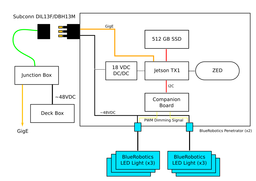
This tether was terminated in a generic breakout box providing both a conventional Cat6 RJ45 connection and a four-pin power connector.
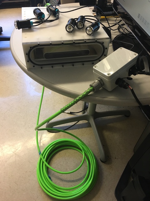
Six-light MaSCOT with new shore cable and junction box (right).
To support MaSCOT, a deckbox was also constructed housing a 150W 48VDC power supply.
This improved MaSCOT has been tested dry but not in the water. The camera is otherwise available for supporting further video processing development.
Publications
The construction of the MaSCOT and the calibration process were detailed in:
Marburg, A. “Dense Realtime Underwater Reconstruction with a Low-Cost Stereo Camera.” MTS/IEEE Oceans 2016 Monterey.
All software produced for this project have been made publicly available through a Github software respository. The modified LSD-SLAM package has been downloaded ~1000 times in the last six months of 2016.
Follow-Ons
MaSCOT data has been shared with BluHaptics, MBARI, NOAA, and the State of Washington Department of Fish and Wildlife (DFW).
The system will be deployed by the DFW in Spring 2017 to investigate ROV-based stereo imagery for fish survey.
The LSD-SLAM software is an essential element for the completion of the grant “Realtime 3D Reconstruction from ROV Camera Arrays of Opportunity” from the NOAA Office of Exploration and Research (OER).
Acknowledgements
This work was generously funded by the APL Science and Engineering Group Internal Research and Development program. Particular thanks to Justin Burnett for designing the enclosure and getting it through the machine shop in record time, and to Robert Karren for taking charge of the final electrical and mechanical assembly. Thank you Jakob Engels for LSD-SLAM and Thomas Whelan for his ROS-free port of same.
References
- See for example OpenSLAM.org
- Icron USB 3.0 Spectra™ 3022
- e.g. Connect-Tech Elroy carrier board
- LSD-SLAM: J. Engel, T. Schöps, D. Cremers. Large-Scale Direct Monocular SLAM. In European Conference on Computer Vision (ECCV), 2014.
- J. Engel, J. Stückler and D. Cremers, Large-scale direct SLAM with stereo cameras. 2015 IEEE/RSJ International Conference on Intelligent Robots and Systems (IROS), Hamburg, 2015, pp. 1935-1942. doi: 10.1109/IROS.2015.7353631
