
| Up to main | |
Chemistry Electronics Services
| |
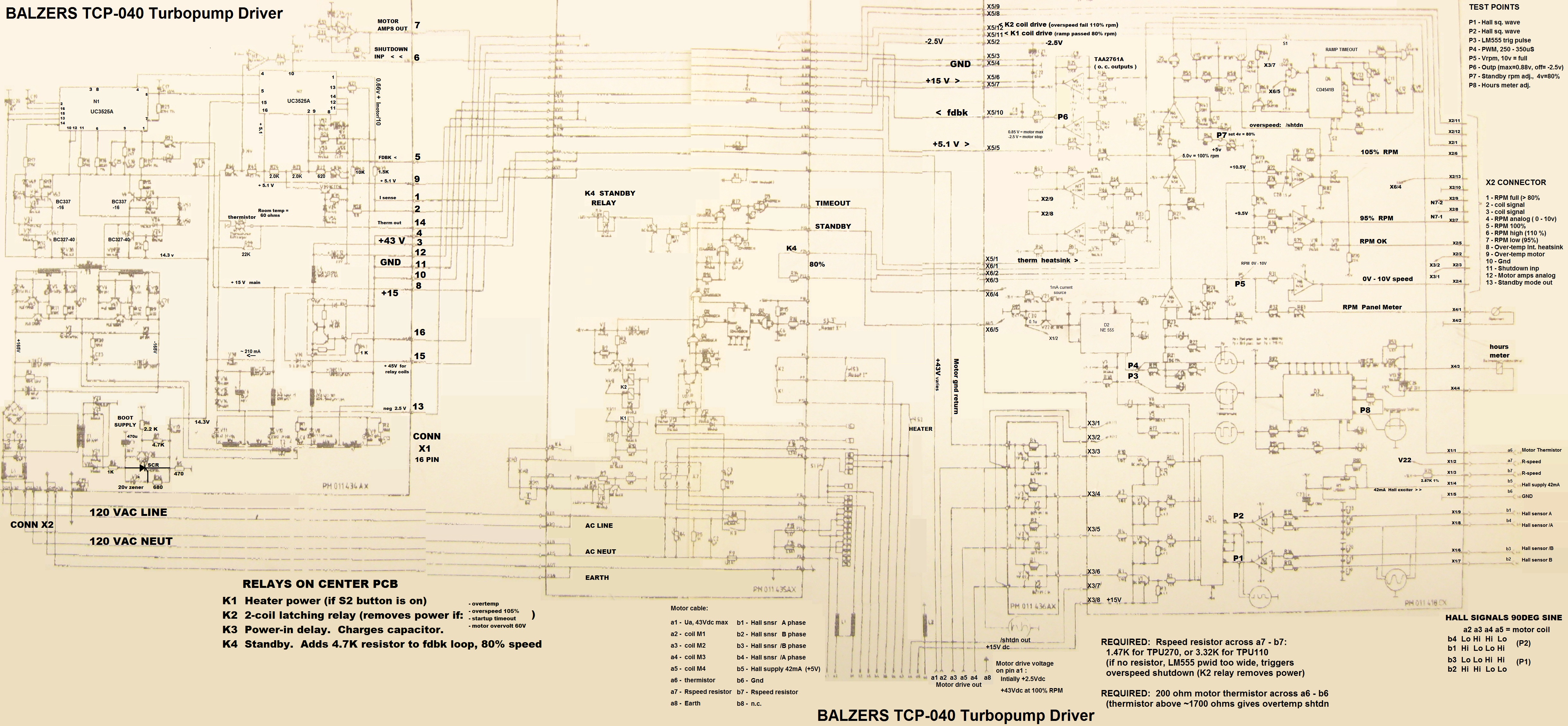
Pfeiffer-Balzers Turbo Pump Controllers TCP-121 and 40CABLE FOR TPC-040 TURBOPUMP DRIVER BALZERS PFEIFFER
Motor Ctrlr Wire color Controller cable, wire colors
Cable Cable Function a b
A a5 BK thk M4 coil 8 GN/YEL GN thick
B a4 BU thk M3 coil 7 BK thin WH thin
C a3,U BR thk M2 coil 6 GY thin BK thick, GN thin
D a2,T PK thk M1 coil 5 BK thk YL thin
E a1,R RD thk 45VDC 4 BU thk RD thin
3 BR/VIO thk BR thin
F b6 GN thin COM 2 PK/GY thk PK thin
M a6 GY thin thermistor 1 YL/RD thk BU thin
G b5 YL thin Hall 42mA drive
H b4 RD thin Hall phase /P2
J b3 BR thin Hall phase /P1 Pump conn, controller rear panel
K b2 PK thin Hall phase P1 a8 case gnd b8 n.c.
L b1 BU thin Hall phase P2 a7 Rspeed b7 Rspeed 1.47K or 3.32K
a6 thermistor b6 thermistor (gnd)
N a7 BK thin Rspeed a5 coil M4 b5 Hall 42mA drive
P b7 WH thin Rspeed a4 coil M3 b4 Hall phase /P2
a3 coil M2 b3 Hall phase /P1
R a1,E YL thick 45VDC a2 coil M1 b2 Hall phase P1
T a2,D GY thick 1 coil a1 DC 3v - 45v b1 Hall phase P2
U a3,C VIO thick 2 coil
V a8 GN/YEL EARTH
S b8 GN thk n. c.
POWER CONN, controller rear panel
a8 case gnd b8 Reset button (pull dn)
a7 PTC to +45VDC b7 "A"
a6 Ext. standby sw. b6 Rly K1 n.o., on=full spd
a5 com ps gnd b5 Rly K1-K2 com
a4 interlock b4 K2 n.o. on=not failed
a3 htr out 120V b3 Panl sw, n.c.
a2 AC inp N b2 Panl sw, AC inp L
a1 AC inp L, jmp to b1 b1 Panl sw n.o., jmp to a1
TCP-121 Turbo Controller
TYPICAL FAILURES:
F1 fuse, main 120VAC (F2 ventvalve? F3 heater?)
SYMPTOMS:Fail after power outage, probably the boot circuit was dead much earlier (100uF cap dried out, or grey 15VAC xfrmr shorted turns.)
Or, the relays repeatedly click, fan jerks, but only if a turbo pump is connected during power-up: overcurrent detected, PIC626 power transistor is probably shorted or SG3525A is dead, and is applying 45VDC directly to the non-spinning turbo (turbo coils normally start up at 1.5VDC, slowly rise to 35VDC giving 1KHz 60kRPM, or 24VDC for "standby" 700Hz.
Fan not spinning. If fan not old/dead, the 24VDC fan is spun by the main +45VDC supply (through a series 220 resistor.) Spinning fan shows that raw 45V is working, good all the way up to the input to the PIC626 power transistor.
PIC626 power "darlington" should show 75 ohms between pin3-pin4, yet NOT be shorted between pin1-pin4.
NOTES:
Power cable: some cables lack the jumper a1 to b1, which normally sends 120V through the front panel sw.
K2 relay is the center relay of the three. Fail-reset: we remove power for 3sec.
SG3525A pwm chips: one IC runs the +45VDC for turbo, other runs +15V for circuitry.
PIC626 "darlington" is saturated/on when its pin3 is pulled down by ~0.7V wrt inp, pulled down by 9.3mA to start conduction. Spec sheet insists at least pulled down by a minimum of 30mA through its Base (minus the 10mA taken by 75ohm resistor,) to guarantee fully on. Stay below 8mA to turn off at 0.6V across Vbe and 75ohm. The 820ohm and 15V zener to gnd gives 36mA (on TCP-040, 1.5K to gnd gives 30mA.)
TWO DIFFERENT DESIGNS, SCHEMATICS! One has pwm chips on a daughterboard, ICL7665 in the boot circuit, and drives the PIC626 pwr transistor-base square wave via an NPN wired for ~30mA constant current. The other type has pwm chips on the main board, the boot circuit has an SCR pulser, and the PIC626 transistor-base square wave is driven by a 15V zener in series with 820ohms.
TURBO'S FEEDBACK: it comes in via four Hall Sensor signals, through dual comparator to create two 90deg quadrature square waves, then converted by CD4028 (bcd-to-decimal) into the 1,2,3,4 pattern of 15V pulses to four coil-drive open-drain transistors.
|
|
|
|
|
Department of Chemistry University of Washington Box 351700 Seattle, Washington, 98195-1700 Voice: (206)543-1610 FAX: (206)685-8665 |