That works by letting one bunch enter a gap between an antenna and the surrounding ground-potential chamber. The antenna and chamber are sized to resonate at that 50 MHz frequency. Hence they're called resonators.
They're formed from forged copper, and ahve a 5-micron thick layer of
Lead electroplated onto them. Then the entire chamber is suspended in Liquid Helium, bringing them to 4 degrees Kelvin.
At that point, the lead becomes superconducting.
That allows all of the electrical energy we pump into the antenna to appear at the resonating end, rather than simply heating up the copper/lead due to resistive losses. This allows us to use a little over 100 watts per antenna, rather than the kilowatts we would have needed for conventional-temperature antennas. The cost of the entire cryogenic facility was cheaper than the air conditioner we would have needed had we gone conventional.
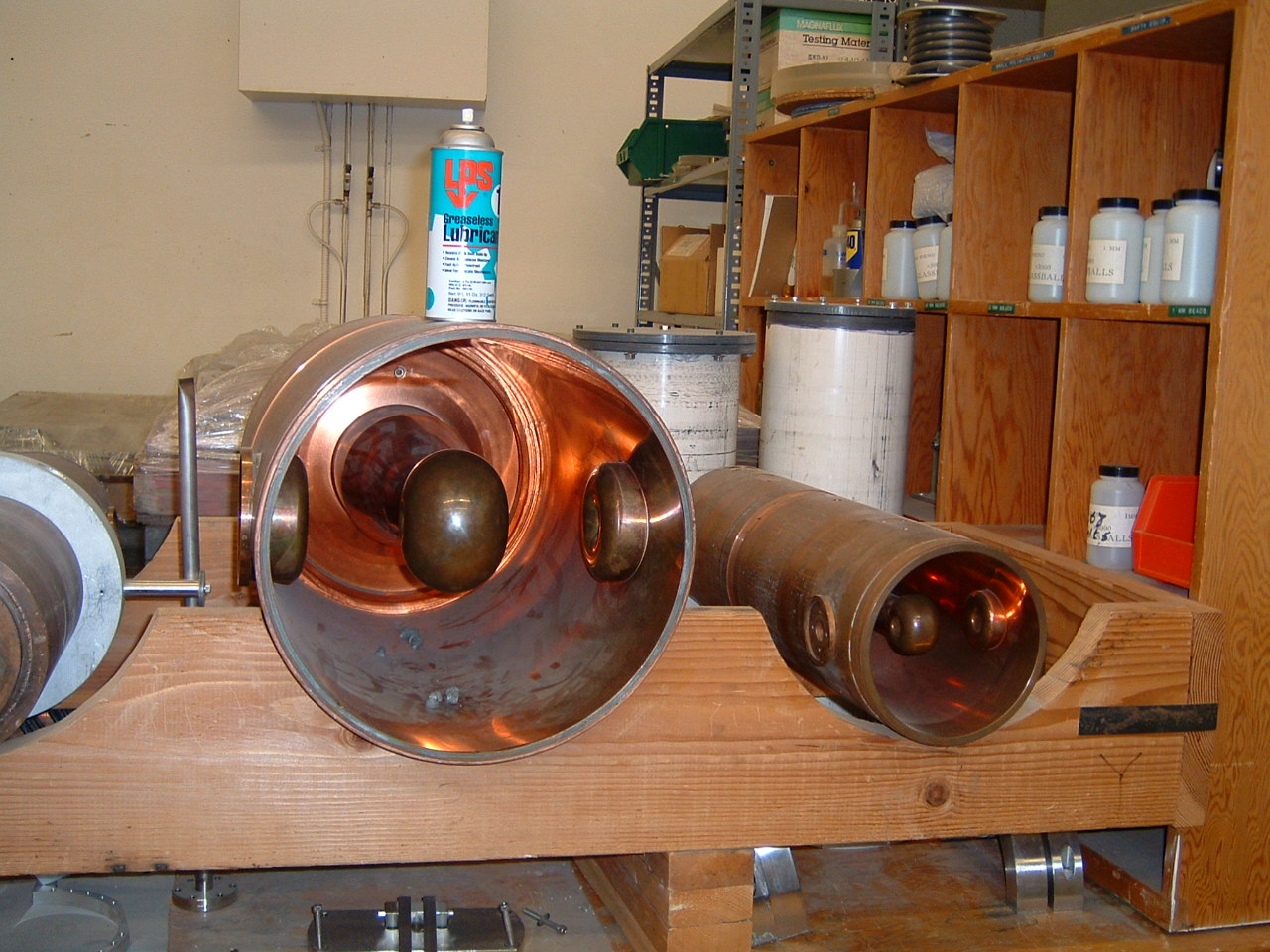
Here are two of the resonating cavities, with a typical spray can for scale.
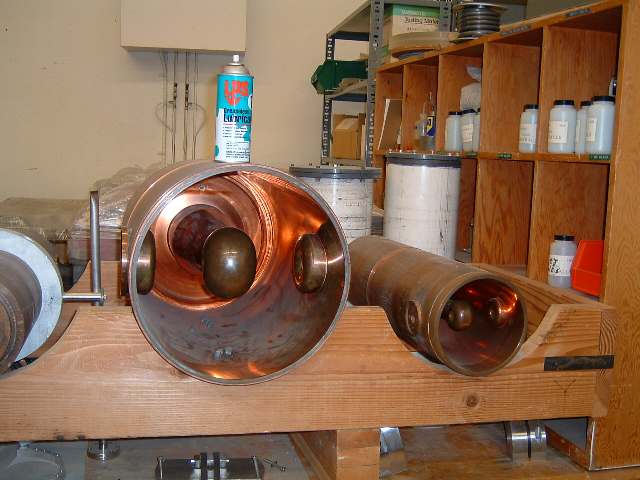
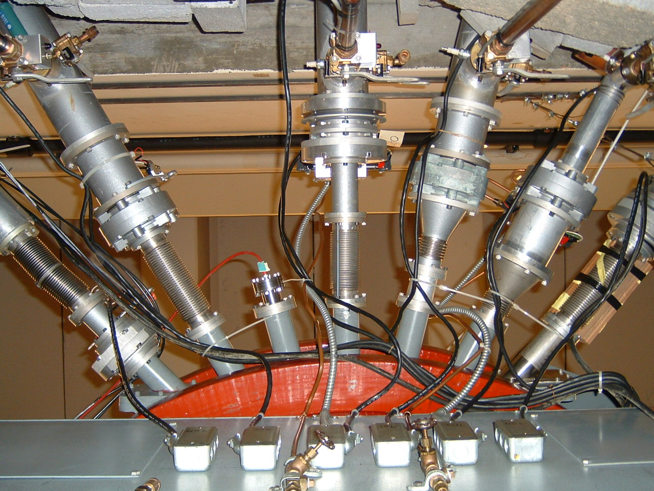
There are two sizes of resonator... the small ones are mounted four in each of six stainless cryogenic containers shown in the other web page, on the "low speed" side of the Linac. Then we loop the beam around and come through another six canisters. But by now the beam is moving quickly enough that the small gap in the small resonators wouldn't have much time to affect the beam.
So we double the size of the resonator, doubling the gap size. There are only two resonators in each of the "high speed" side's cryogenic canisters.
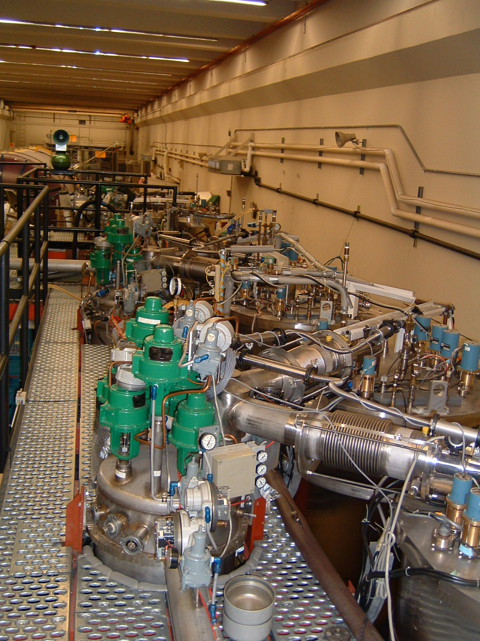
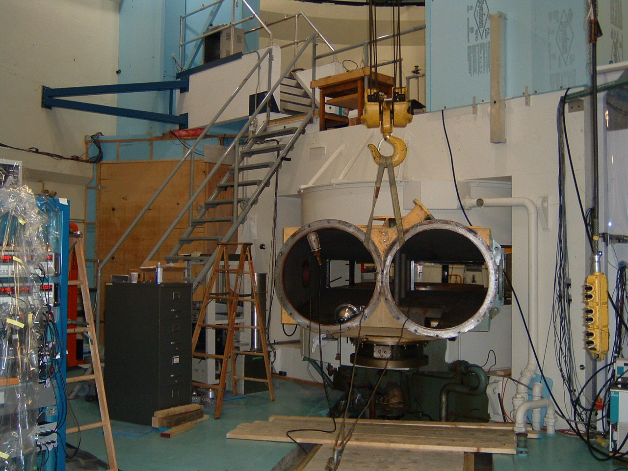
Here's a view of the catwalk above the cryogenic canisters.

The clutter is the hardware needed to "tune" the resonators (done by mechanically warping the end of the resonator's copper chamber),
and to distribute the liquid helium, return the gaseous helium for re-compression back to liquid, and plumbing for liquid nitrogen, which serves as an "insulator" between the liquid helium and the outside air.
Reliquifying the helium caused us to create what turned out to be the 3rd largest liquid helium facility on the west coast. Helium is liquified by simply squeezing it. The "refrigerator" is "merely" a set of four VERY powerful pistons being driven by a few horsepower of motor.
The squeezing heats up the helium, and conventional heat-exchanger
technology removes that heat from the cylinder walls. The pressurized helium eventually just "dribbles" out the bottom of the cylinders.
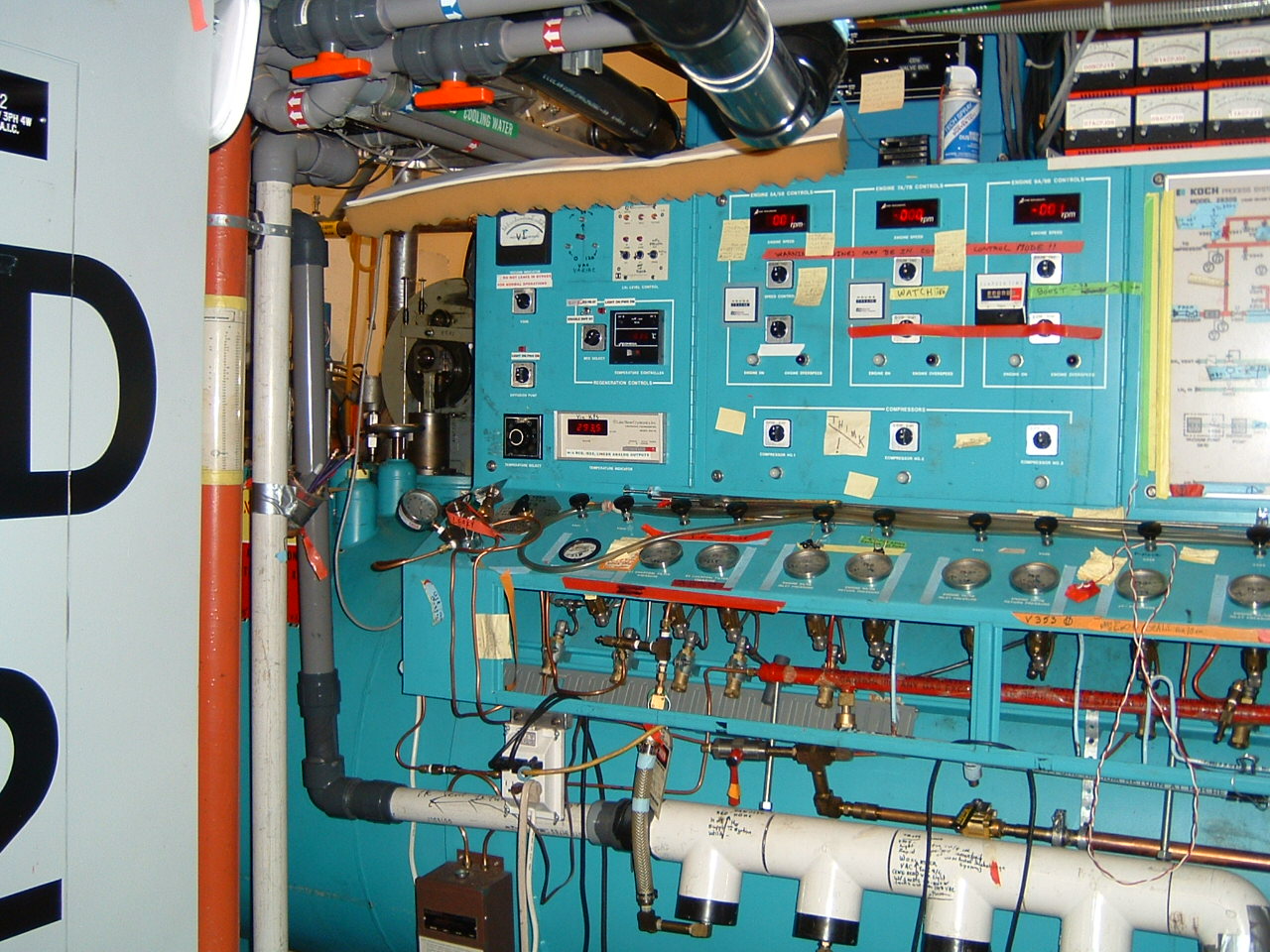
Here's that refrigerator.

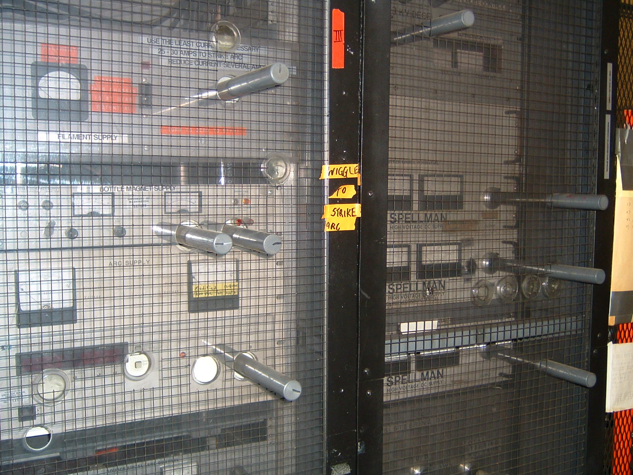
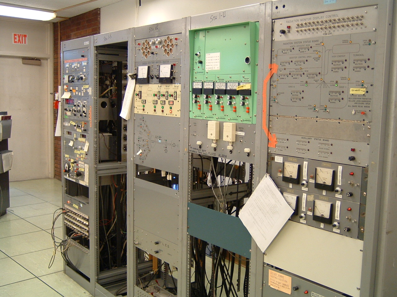
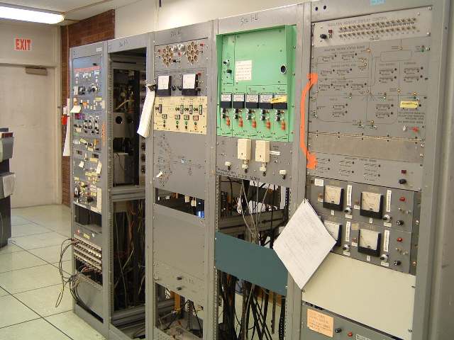
All of the resonator frequency and phasing control is handled by six duplicated computer, amplifier, vacuum and cryogenic systems.
Each station has a mid-seventies era PDP 11/21 controlling it.

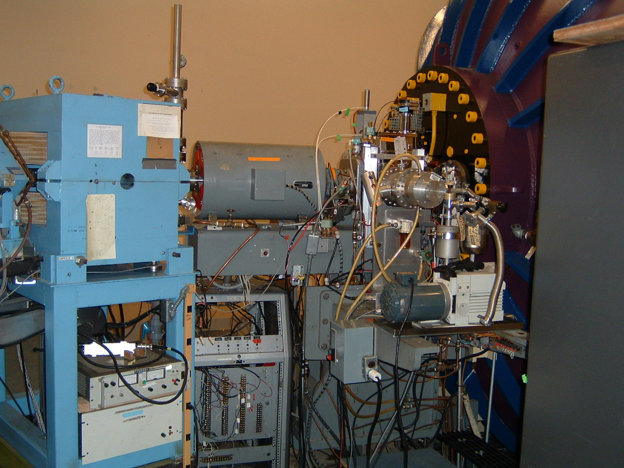
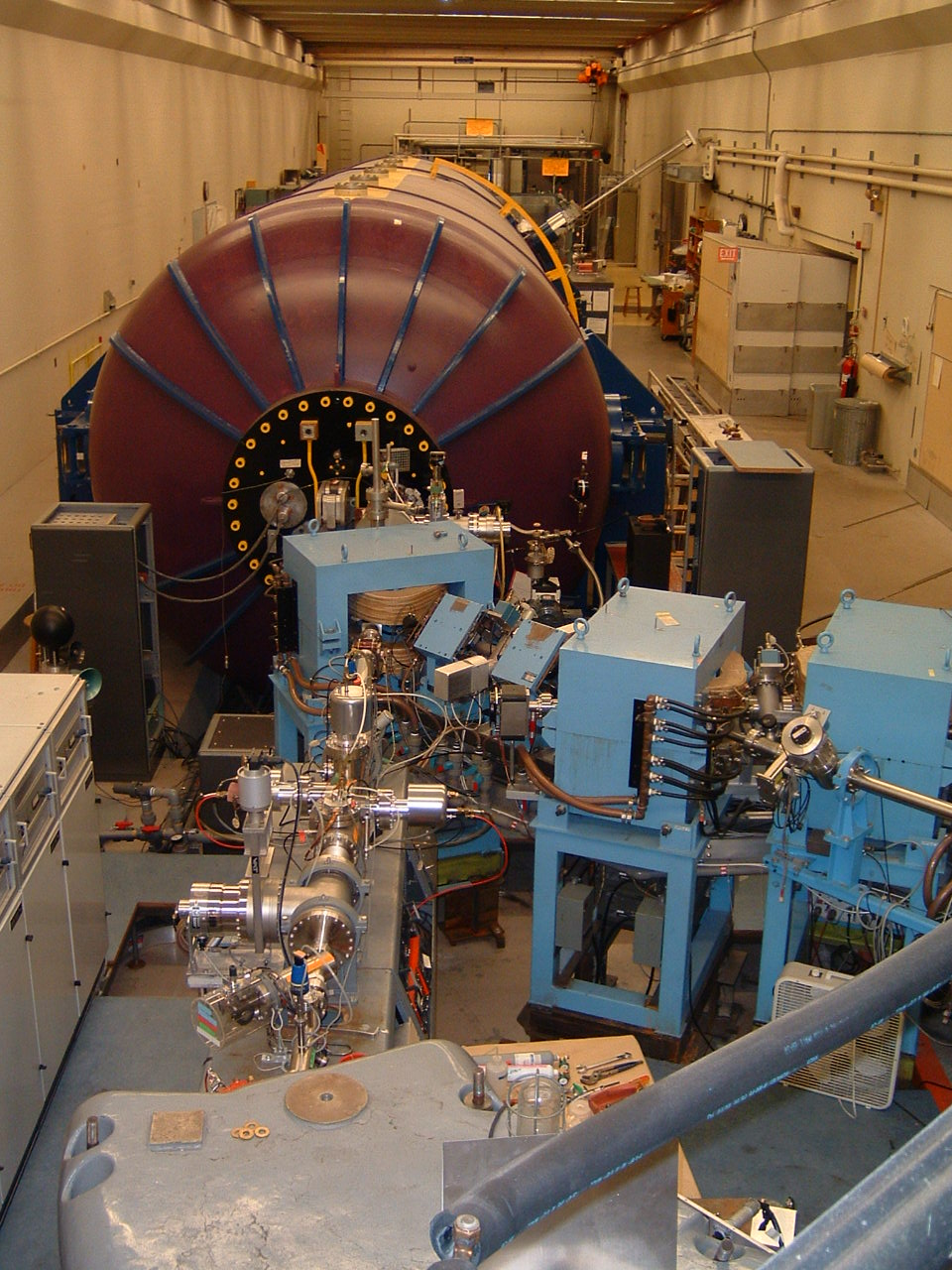
After all of that, the beam rejoins the original unLinac'ed
beam pipe to pass through the final switching magnet.

Each pipe leads to one of the target areas in the target rooms.
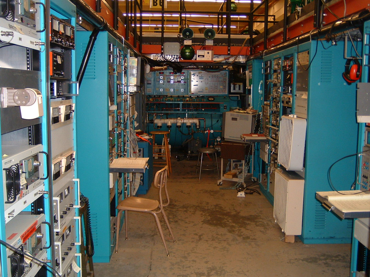
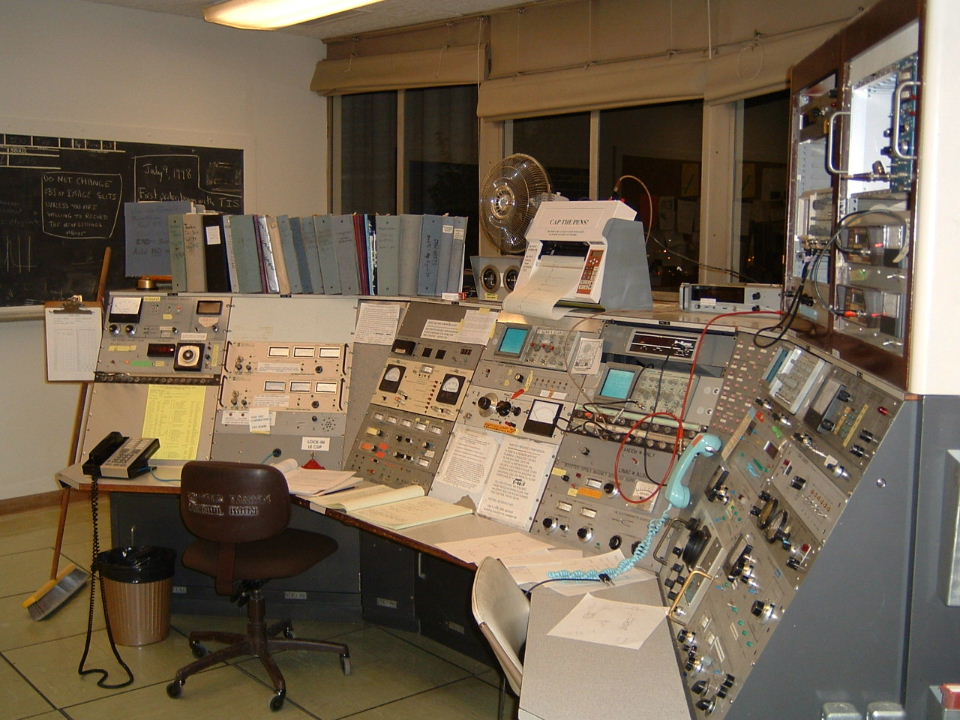
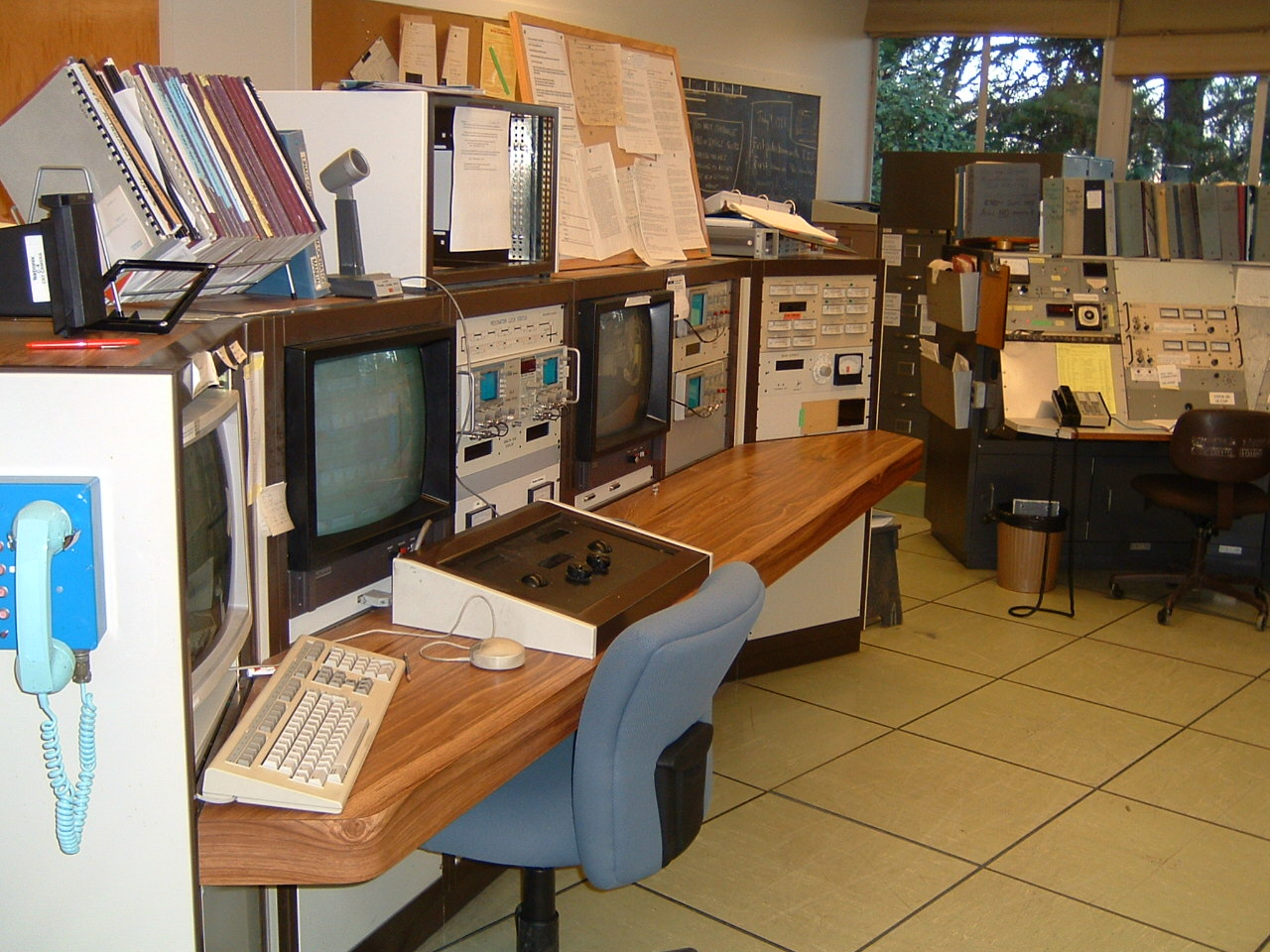
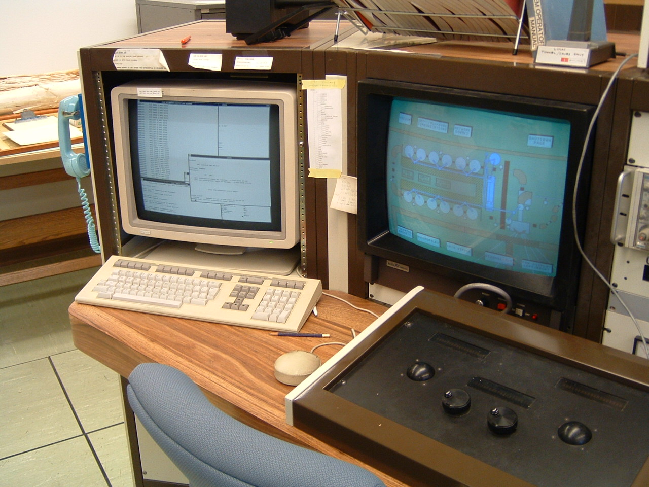
We now return to where the people -really- sit, the control room.
It has banks of interlocks to monitor doors and gateways to turn
off the accelerator if anyone goes where they shouldn't.
It has the low-tech control panel shown here:

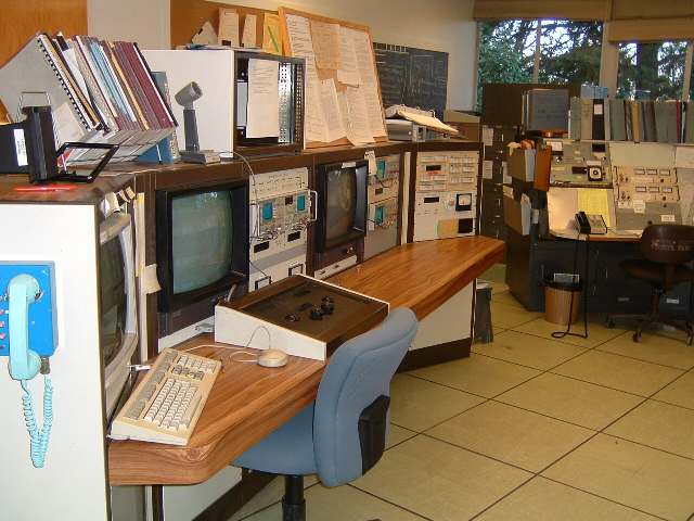
and this dual color touch-screen, highly flexible control system controlled
by an embedded PC-on-a-cards running DOS, and a DEC microVAX.
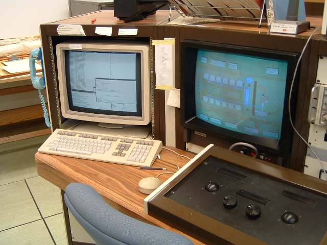
Although hard to see, the black panel beneath the right-hand screen
is a programmable set of knobs, trackballs and displays.
By tapping on spots on the scrren, any control of the machine may be routed to that panel,
if the operator would rather twist a dial instead of click a cursor.
Our lab has been here since 1950... it started with a 50-inch cylcotron,
duplicating the one at Berkeley. This is currently being dismantled to
make room for super-precise gravity measuring equipment.
My work here at the UW started as a computer geek for a cancer therapy experiment.
We generated "slow neutrons" with the cyclotron to shoot at untreatable cancers.
Since then the hospital bought their own cyclotron, and this venerable machine has
not been turned on since 1977. It's still radioactive.

That's a 40-ton magnet you're seeing. In its heyday, the actual beam
accelerating duties were performed by a 175 kilowatt radio transmitter
oscillating at 38 MHz, flipping the polarity of two half-pizza shaped
"Dees" where those round holes are.
That circular room is even further underground than the Van de Graaf.
IT's buried in a hill, with a three-foot deep lake above it.
Water is a better neutron-absorber than dirt or lead.
Cheaper, too.
We also look at the sun... from 6200 feet underground at
the Creighton Nickel Mine in Sudbury Ontario.
We watch neutrinos pass through 1,000 tons of heavy water.
(D2O). Although 50,000 pass through every cubic centimeter
of your body every second, we catch maybe 12 a day in that 1,000 tons.
They just don't interact unless they -nail- a nuclear particle head-on.
And then we just see the by-products of the collision, as the hit particles
pass through the water at faster than the speed of light -in- water.
That emits a cone of blue Cherenkov radiation, just like a sonic boom
in air. The 1000 tons of water are held in a huge transparent acrylic
bottle, itself floating in a cavern of regular water.
In that cavern are 7,000 photomultiplier tubes, watching for the glow.
Here in Seattle, we have a miniature ball of the photomultipliers,
put together during the design and development stage of the project.
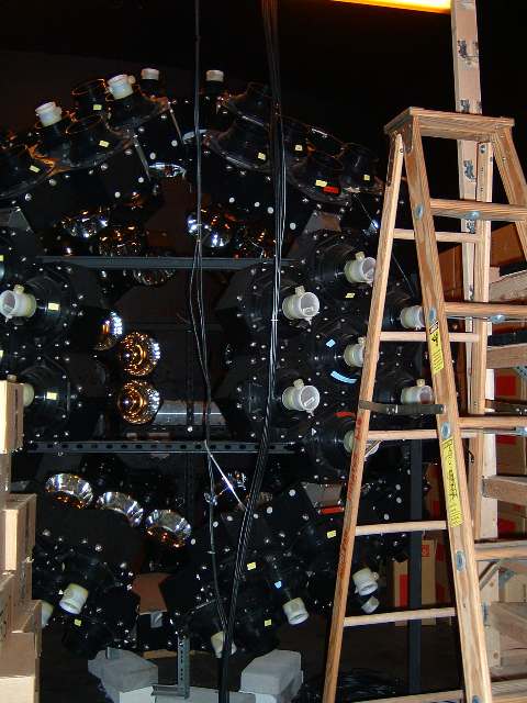
They are in a room which can be, and used to be, flooded with water.
It was originally additional shielding for the cyclotron.
That's the end of today's tour.
=======================
previous page,
Dick's home page