Documentation for timer box
as constructed for Rechele Brooks, Ph.D. as of 3/21/12
by
Fritz Reitz, Ph.D., Research Engineer
Instrumentation Development Lab
Center on Human Development and Disability, SB-202
University of Washington
mailstop 357920
Seattle, WA, 98195-7920
(206) 543-9023
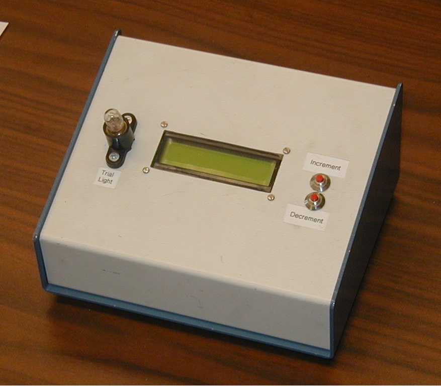
The enclosure has a small 6.3V 0.25A incandescent bulb (left), Powertip PC1602Q B LCD screen ( http://www.powertipusa.com/pdf/pc1602q.pdf ), and momentary, N.O. (normally open) pushbuttons to increment and decrement trial time (red buttons at right).
On the back of the box are 3 connectors, all were eventually upgraded to BNC-style for robustness.
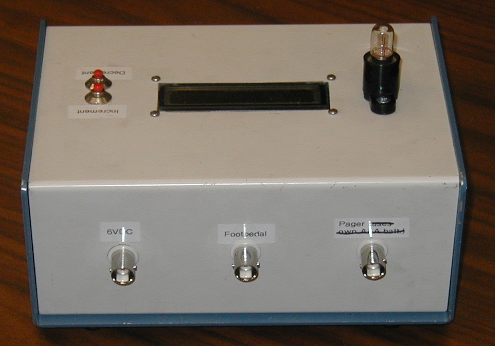
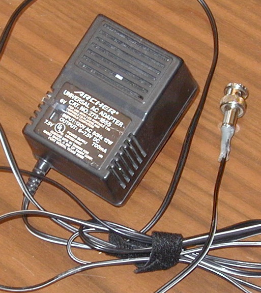
Three external devices plug in to these connectors: a 6V, 700 mA power supply, a momentary, N.O. footswitch, and a pager buzzer.
The power supply:
The footswitch:
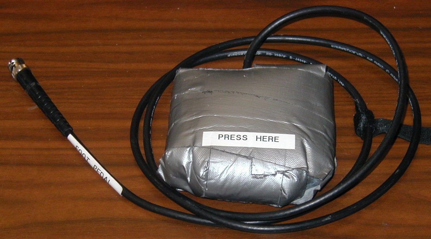
The footswitch is encased in a shell of foam and duck tape to silence its operation.
The footswitch partially opened:
The footswitch pulled out and flipped upright:
A section of 1/2-round wooden trim was attached to the end of the pedal to enhance reliability of operation, lest pressure be applied at or above the hinge of the pedal instead of the end.
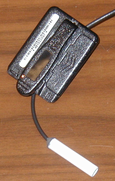
The pager buzzer is a Radio Shack micro-vibration motor ( http://www.radioshack.com/product/index.jsp?productId=2914700 ) :
The motor is encased in a short length of white disposable pen shaft and anchored/strain-relieved with hot glue. The cable is further strain-relieved by attachment to the clip/back panel of a pager with a self-adhesive anchor and zip tie.
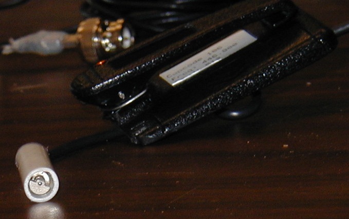
End view of the motor/pen section:
Inside the enclosure are a Parallax BoE (Board of Education) with a BS2 stamp microcontroller, an LM317 voltage regulator, and two IRFIZ34N mosfets.
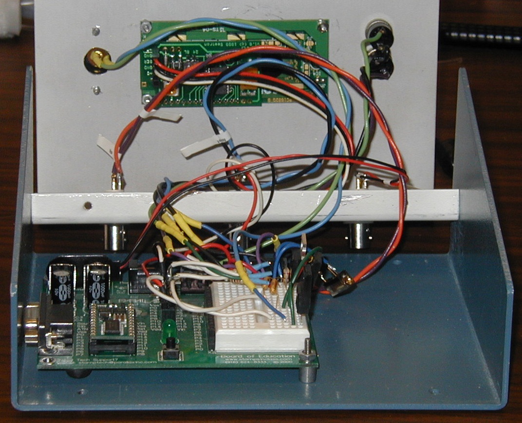
The voltage regulator is adjusted to 3V with a 240 ohm resistor, a 5Kohm trimpot, and 2 0.1uF capacitors.
Pins 3, 7, and 11 of the BoE are pulled high (to Vdd) via 10Kohm resistors such that they can be pulled low (to ground) via the increment button, decrement button, and footswitch, respectively.
One IRFIZ34A switches the ground of the vibration motor. The other lead of the motor is connected to the LM317's 3V output. The IRFIZ34A's gate connects to BoE pin 15.
The other IRFIZ34A switches the ground of the incandescent bulb. The other lead of the bulb is connected to Vin (6V). This IRFIZ34A's gate connects to BoE pin 12.
The red, black, and white leads from the LCD display connect to the BoE's Vdd (5V), Vss (ground), and BoE pin 0, respectively.
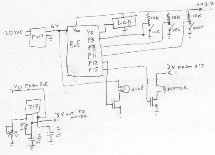
The circuit diagram:
The BS2 was loaded with the software below via the Parallax Basic Stamp Editor development environment ( http://www.parallax.com/BASICStampEditorSoftware/tabid/789/Default.aspx )
' IDL-2387 : Experiment Timer
' 10/15/09 F. Reitz
' {$Stamp bs2}
'
' modified IDL-2276 to shorten buzz duration to 1/2 sec from 1 sec
'
' uses:
' BPKDEMS2.BS2 - came with LCD display
' assumes that the BPI-216 is connected to I/O pin
' P0 of the Stamp, and that it is set for 9600 bps.
INPUT 3 'switch to increment trial length (negative logic)
INPUT 7 'switch to decrement trial length (negative logic)
INPUT 11 'footpedal to start/abort trials (negative logic)
OUTPUT 15 'signal to buzzer (positive logic)
OUTPUT 12 'signal to trial light (positive logic)
OUT15 = 0
' Start by defining some useful constants for the Backpack.
N9600 CON $4054 ' Baudmode-9600 bps inverted. Use $40F0 for BS2-SX.
I CON 254 ' Instruction prefix value.
CLR CON 1 ' LCD clear-screen instruction.
LINE2 CON 192 ' Address of 1st char of 2nd line.
L2_C8 CON 199 ' Address of line 2, character 8.
BuzzerDuration CON 1
TrialLength VAR Byte
TrialLength = 10 ' default number of seconds for trial
TrialLengthInc VAR Byte
TrialTimer VAR Word
'
' Now clear the screen in case there's text left from a previous
' run of the program. Note that there's a 1-second PAUSE prior to
' sending any data to the Backpack. This gives the Backpack plenty
' of time to initialize the LCD after power up.
'
Initialization:
OUT12 = 0
TrialLengthInc = 1
PAUSE 1500
SEROUT 0,n9600,[I,CLR] ' Clear the LCD screen.
PAUSE 1
SEROUT 0,n9600,["Experiment Timer"] ' Print message.
SEROUT 0,n9600,[I,LINE2,"IDL W.O. #2387"] ' Move to line 2 and print.
PAUSE 1500 ' Wait 1.5 secs.
Standby:
SEROUT 0,n9600,[I,CLR] ' Clear the LCD screen.
PAUSE 1
SEROUT 0,n9600,["Trial Length (s)"] ' Print message.
SEROUT 0,n9600,[I,LINE2,"-----> "] ' Move to line 2 and print.
GettingTrialLength:
IF TrialLength > 29 THEN ByFives
TrialLengthInc = 1
GOTO Bygone
ByFives:
TrialLengthInc = 5
Bygone:
SEROUT 0,n9600,[I,L2_C8] ' Move to line 1, character 8.
SEROUT 0,n9600,[DEC TrialLength," "] ' Print value of b2 followed by 2 spaces.
IF IN3 = 1 THEN DontIncrement
TrialLength = TrialLength+TrialLengthInc
DontIncrement:
IF IN7 = 1 THEN DontDecrement
IF TrialLength > 30 THEN DecTrialLength:
TrialLengthInc = 1
DecTrialLength:
TrialLength = TrialLength-TrialLengthInc
DontDecrement:
PAUSE 150
IF IN11 = 1 THEN GettingTrialLength
Running:
SEROUT 0,n9600,[I,CLR] ' Clear the LCD screen.
PAUSE 1
SEROUT 0,n9600,["Elapsed seconds"] ' Print message.
SEROUT 0,n9600,[I,LINE2,"-----> "] ' Move to line 2 and print.
OUT15 = 1
OUT12 = 1
FOR TrialTimer = 0 TO TrialLength*10 ' experiment proceeds in 100 ms intervals
IF TrialTimer < BuzzerDuration*5 THEN Continue: 'was *10, modified 10/15/09
OUT15 = 0
IF IN11 = 0 THEN Abort
Continue:
SEROUT 0,n9600,[I,L2_C8] ' Move to line 1, character 8.
SEROUT 0,n9600,[DEC TrialTimer/10," "] ' Print value of TrialTimer/10 followed by 2 spaces.
PAUSE 87
NEXT
SEROUT 0,n9600,[I,CLR] ' Clear the LCD screen.
PAUSE 1
SEROUT 0,n9600,["Time's up"] ' Print message.
OUT15 = 1
OUT12 = 0
PAUSE BuzzerDuration*500 'was *1000, modified 10/15/09
OUT15 = 0
GOTO Standby
Abort:
OUT15 = 1
OUT12 = 0
PAUSE BuzzerDuration*200
OUT15 = 0
GOTO Standby