POST
MaSCOT Report, Part 3: The Companion Board
TL;DR: I ended up needing to to design a micro-based “companion board” which handles power-on, watchdogging, out of band comms, and LED light control for the Jetson. The details can be found on GitHub.
A primary concern for me was ensuring the system was as usable as possible while inside the housing. Opening and closing the housing is time-consuming and somewhat risky in terms of getting a repeatable seal. Unfortunately, the ethernet-only architecture severely limited my options for out-of-band communications to the system. That is, if the Jetons failed to boot, there would be no ethernet, and I’d be hosed.
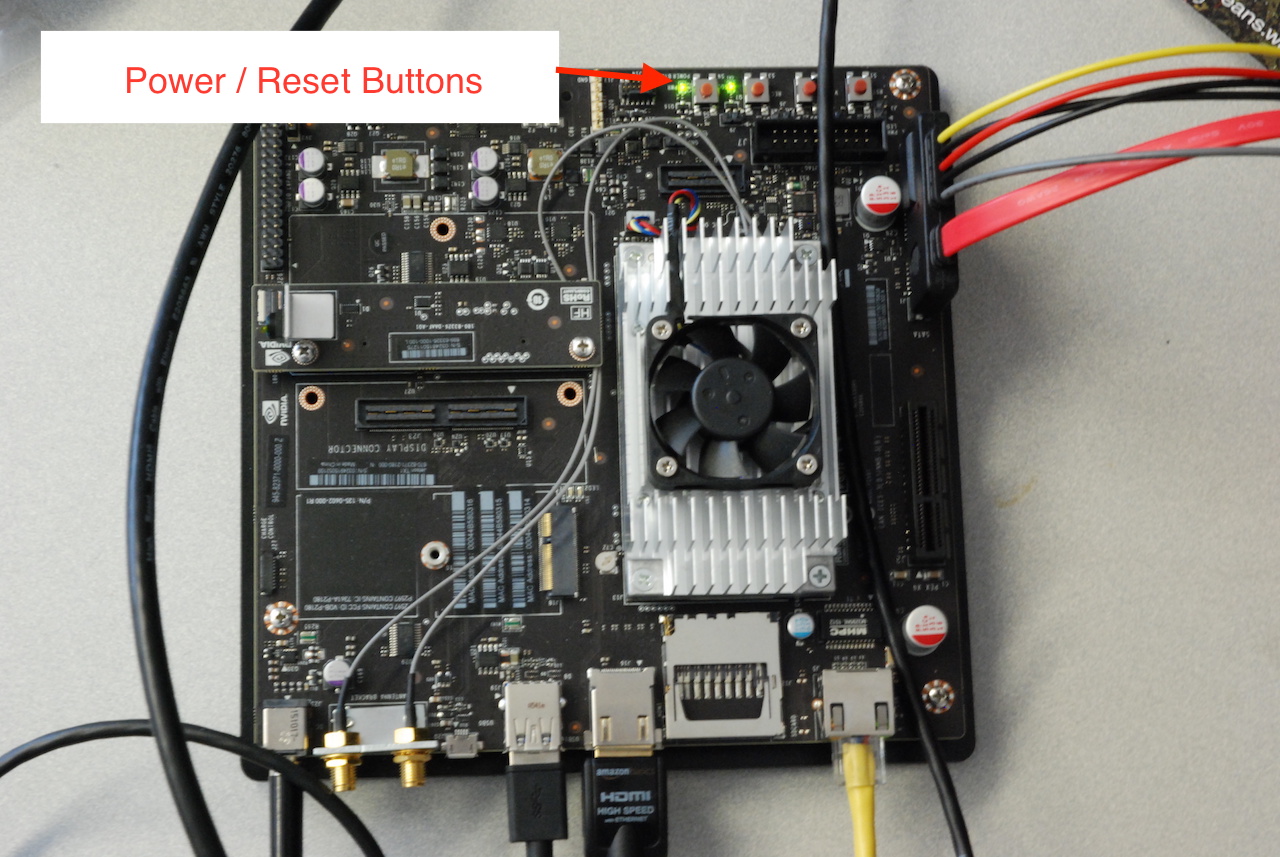
During initial testing of the Jetson+Zed+PoE, I had a proverbial moment where the penny dropped. The Jetson board has a manual, momentary power-on switch on the board.
{:.center}

A quick look through the Google revealed there’s no way (in software) to have the board turn on automatically when power is applied. The approved method is to interface with the power management unit through the tiny, fiddly Samtec debug header.
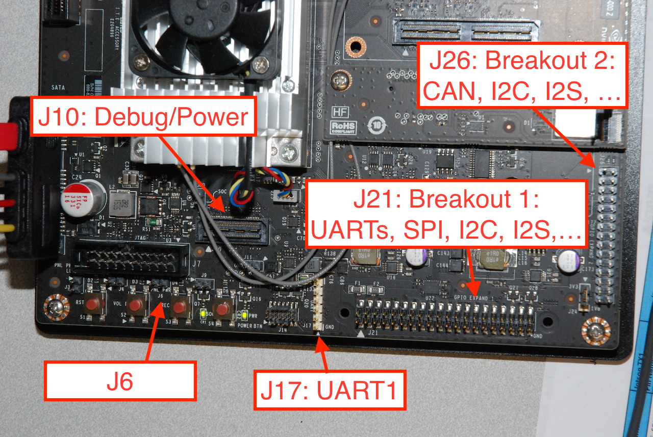
As all of the system breakout headers are clustered in one corner of the board, this quickly expanded into the idea of designing a breakout board which would sit on a number of the headers (including the J10, the Samtec debug header).

Essentially any microprocessor architecture would do, but I decided it was finally time to try out a couple of MSP430FR chips I had lying about, so that settled that.
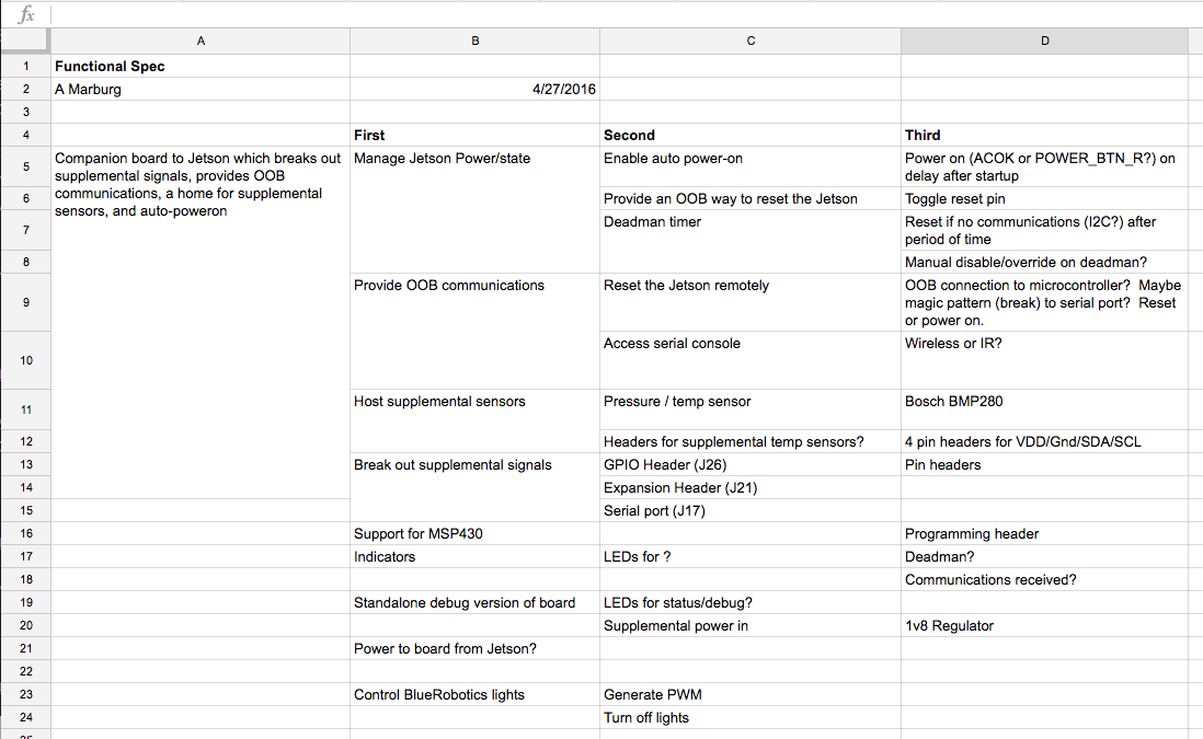
With that in mind, here is the original set of specifications for the board:
{:.center}

Very quickly I realized working with the Samtec debug header was going to make the job much harder. At first I despaired that I would need to blue wire onto the switch itself, then I realized there was a 2-pin header (J6) which bypassed the switch:
{:.center}

Neat!
The remaining specs add nice features:
- The board provides full breakout for the 0.1" pin headers on the Jetson dev board.
- It has its fingers on the power and reset circuits for the board, so in addition to auto power-on, it can act as a remote reset or watchdog.
- I added an I2C pressure and temperature sensor as it would let give me a separate measurement of air temperature in the board (in addition to the die sensors built into the Tegra), and a pressure sensor should I ever use vacuum to verify the seal on the enclosure (I didn’t do this as a matter of practice, and there isn’t a vacuum port on the enclosure as designed).
- I added an XBee footprint in part because I had a few lying around, but because it gives me a back door to the Jetson’s serial/console port. I had originally planned to use the XBee’s “transparent” digital I/O capability to send remote commands to the MSP430 as well — for example, reset now, or disable the watchdog — but I never got that function working on the XBee.
- The BlueRobotics Lumen R1 lights can be on/off, or can take a servo-style PWM signal to control brightness. Rather than beat my head against the PWM controllers on the Tegra, I generate two PWM signals (left and right light) with the MSP430.
- Care and feeding for the MSP430, and a programming header
- Some blinkenlights
Both the MSP430 and the BM280 pressure/temp sensor hang on one of the Jetson’s I2C bus.
More in part 4