BEE 531 Ultrasound Pulse-echo
Instructor: Matthew Bruce / mbruce@uw.edu
University of Washington
Agenda for tonight
- Review from previous lecture.
- Pulse echo in 2D.
- Grating lobes.
- Review for exam.
- Exam Review
Pulse Echo Focus 3cm
Pulse Echo Focus 6cm
Pulse Echo Focus 100cm
Pulse Echo Steer
Pulse Echo
Pulse Echo off axis
Axial Resolution
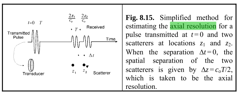
Interval between the end of the first recieved echo and start of the second: \( \Delta t = 2 \Delta z / c_0 - T \)
When $\Delta$ t is zero : \( \Delta z = c_0 T/2 \)
Lateral Resolution
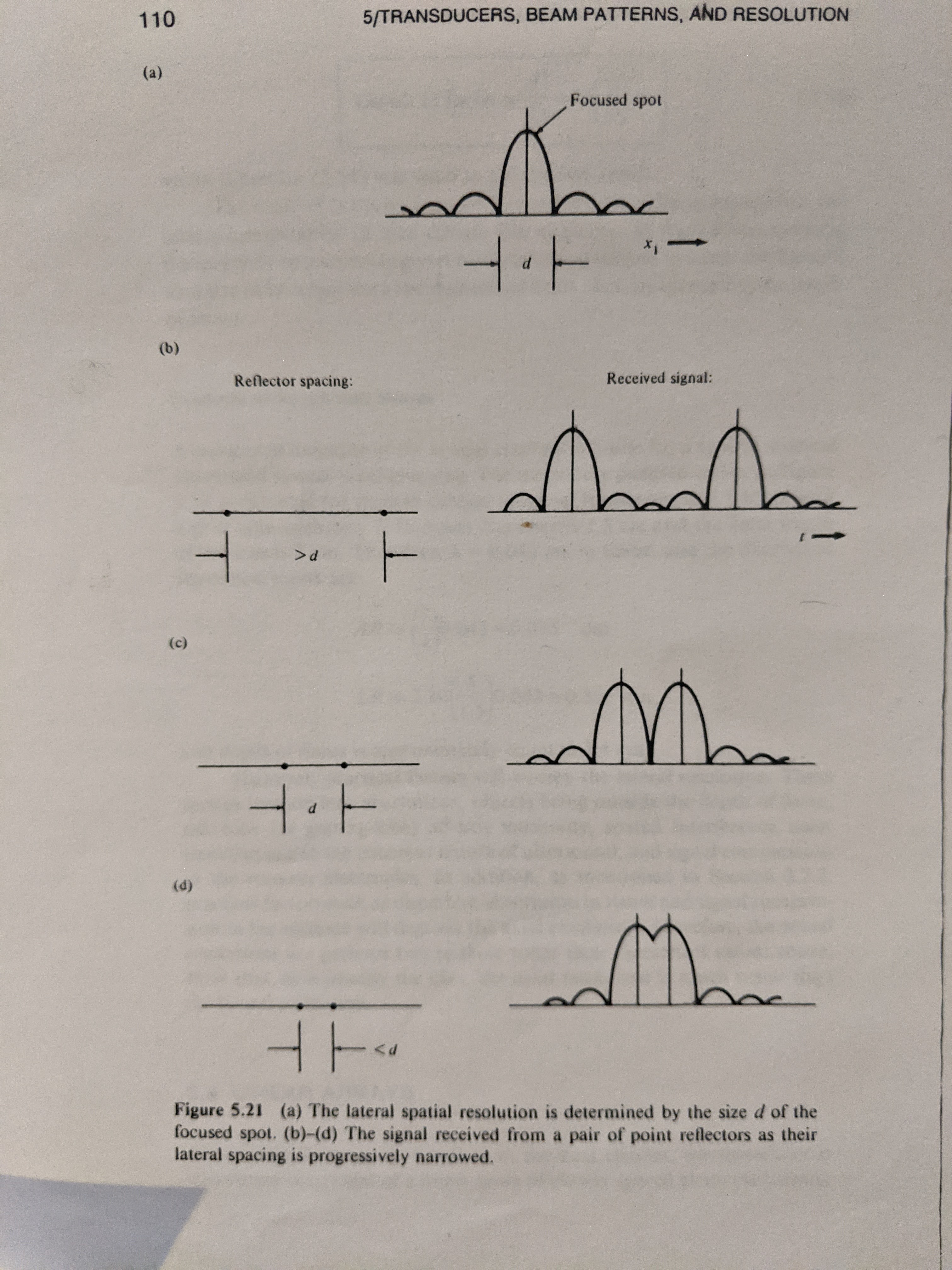
Lateral Resolution
\( S = \frac{\sin \frac{1}{2} \Phi}{\sin \frac{1}{2} \Phi / N}= \frac{\sin \frac{1}{2} \Phi}{\frac{1}{2} \Phi } \; \; \; \; \Phi = 2 \pi \frac{D \sin \theta}{ \lambda }\)
\( \Delta \theta = \frac{\lambda}{D} \)
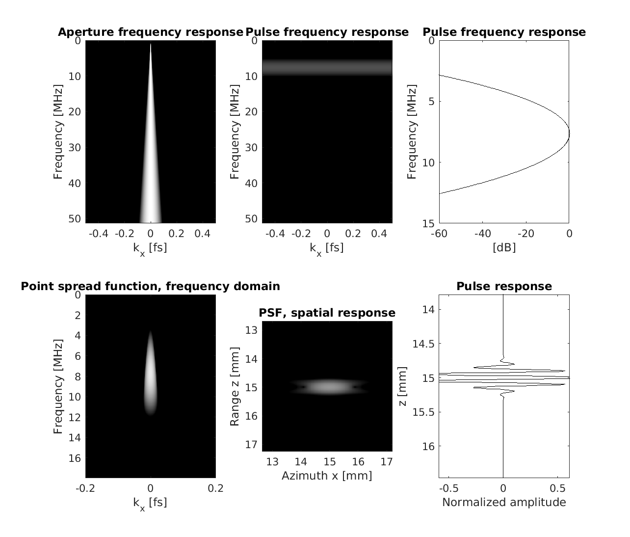
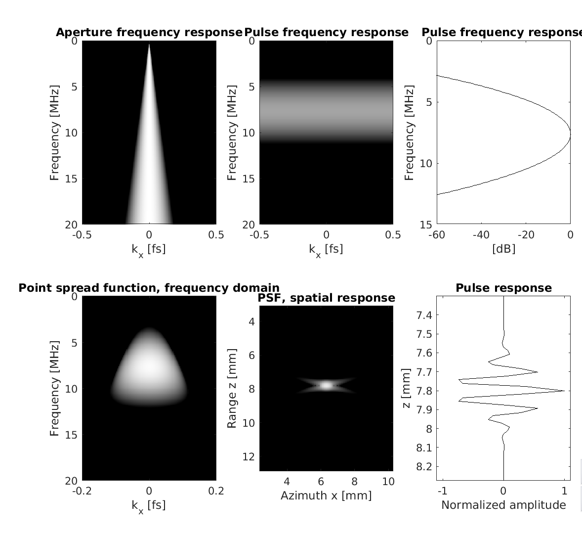
System point spread function
Point spread small aperture
Point spread big aperture
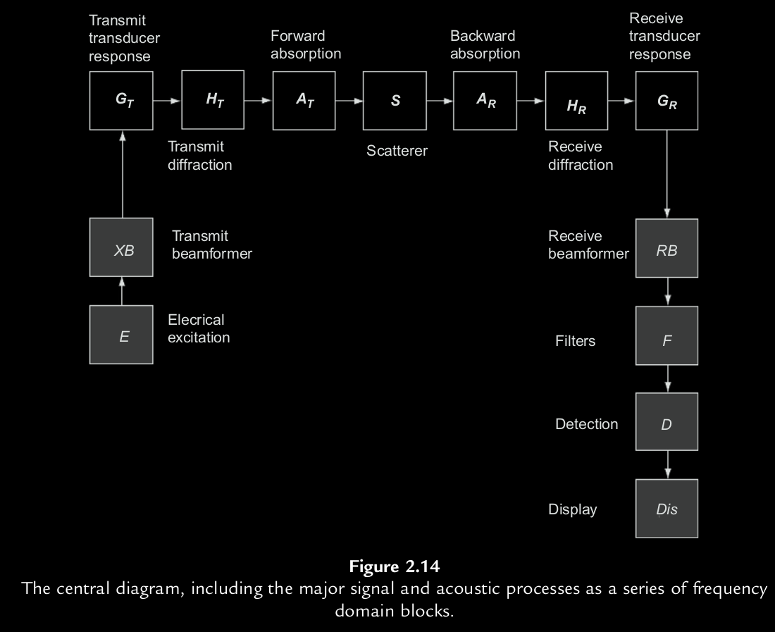
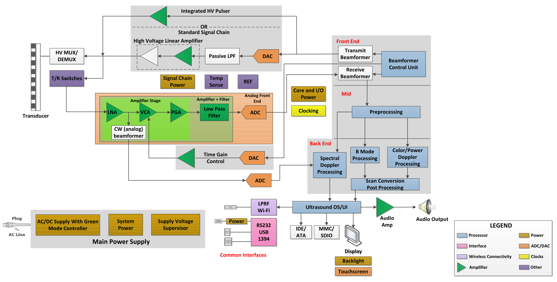
Ultrasound system architecture

Ultrasound system hardware
Receive Beamforming key ideas
- Dynamic receive focusing
- Digitally focus at every reconstructed point
- Apply geometricaly delays to focus at a point.
- Align returning wavefronts from a particular point
- Dynamic receive apodization
- Change aperture width with depth.
Linear Verasonics probe (L11-5v)
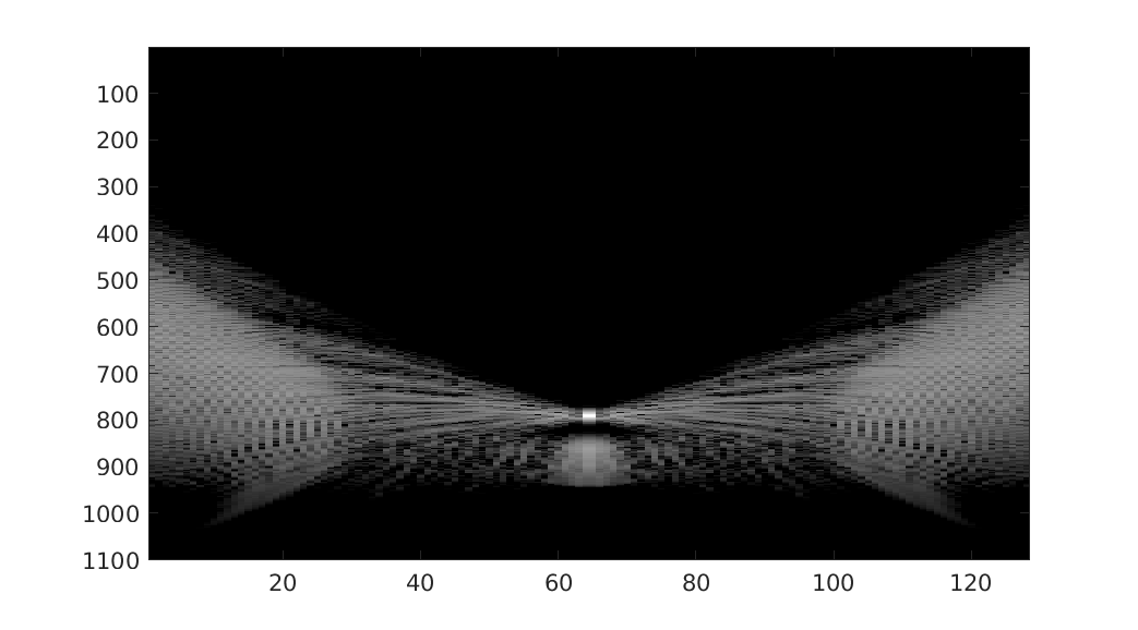
Raw RF from each element
Delay and sum Beamformer
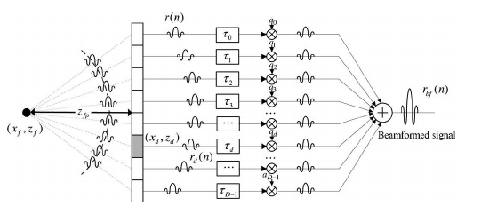
where $x_c$ is the location of the center of each element, $(x_f,z_f)$ is the recieve focus for an image point.
Delays to flatten RF
where $x_c$ is the location of the center of each element, $(x,z)$ is the image point.
Flattened/delayed RF
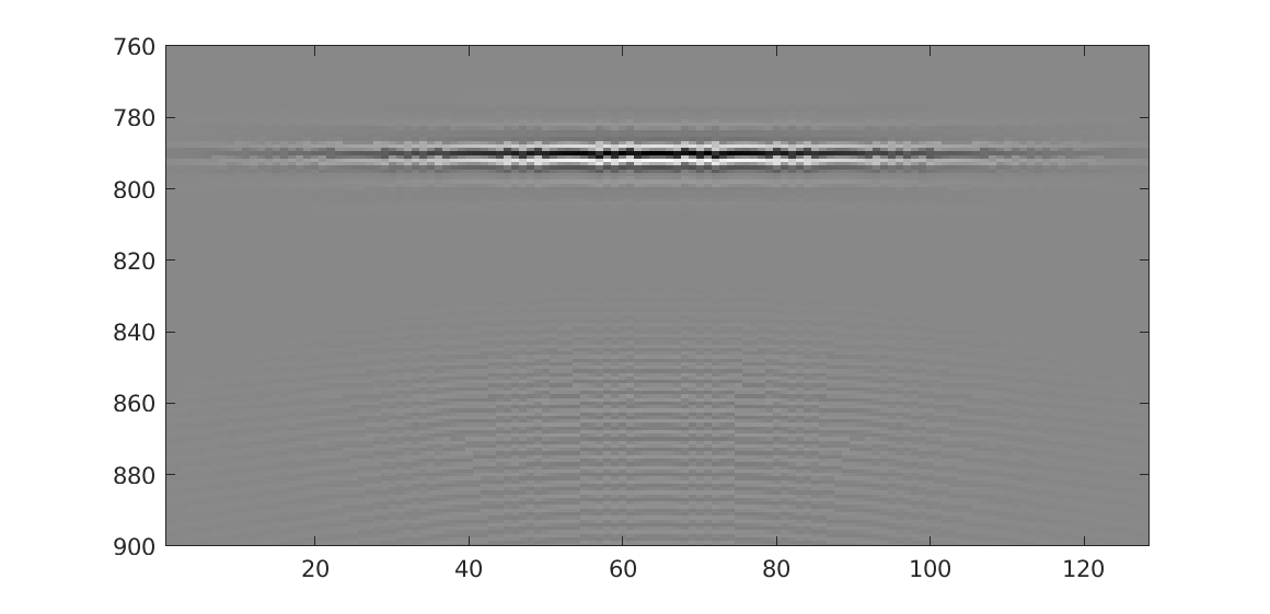
\( img(t_i,l) = \sum_{el=el_{st}}^{el_{end}} w(t_i,el) X(t_i+\Delta(t_i,el),el) \) where $img(x,z)$ for each point in depth and lateral position is defined by: $\Delta(t_i,el)$ a delay matrix with elements defined by $\sqrt{{x_c-x}^2+z^2}/c -z/c$, $X$ the input RF matrix, and $w$ the receive apodization.
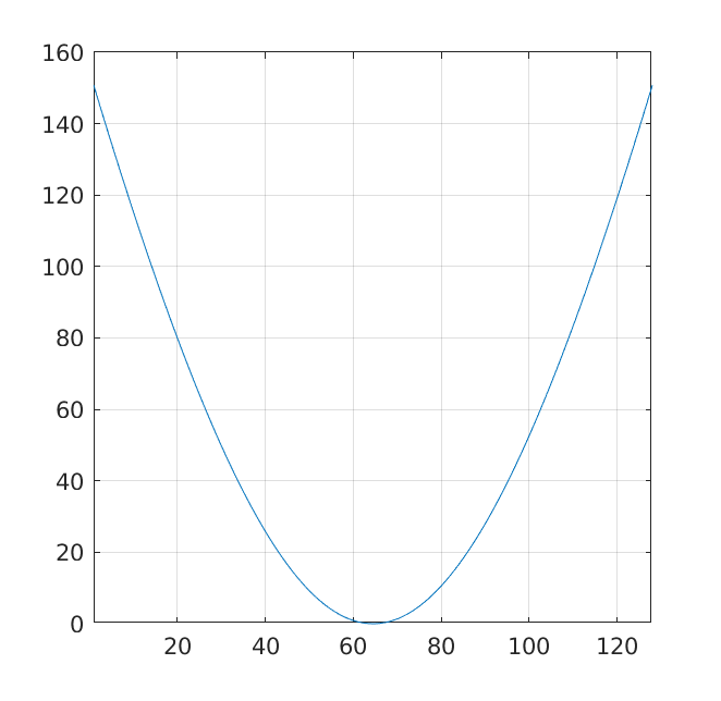
Delay matrix
\( \Delta(t_i,el) \)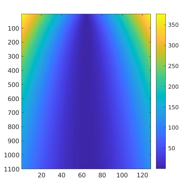
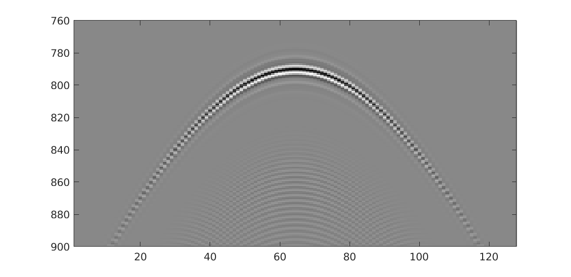
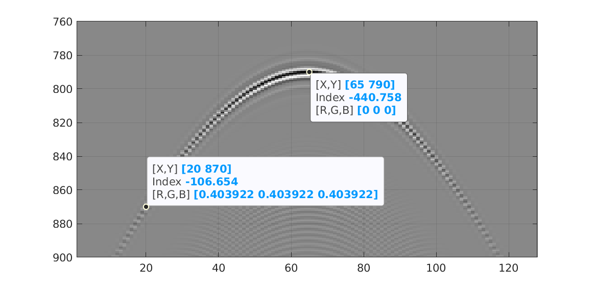
Delay at point scatterer
Delay at point scatterer
Linear Verasonics probe (L11-5v)
Apply delays over depth for each line
Bmode Signal Path
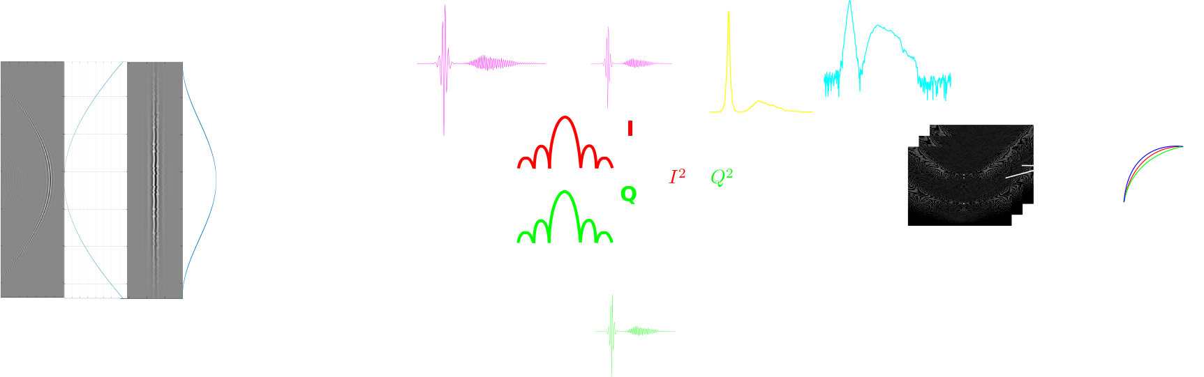
After mappng to RGB, images are ready to be displayed onto monitor. The cineloop is generally placed anywhere after after beamformation/IQ.
Effect of log
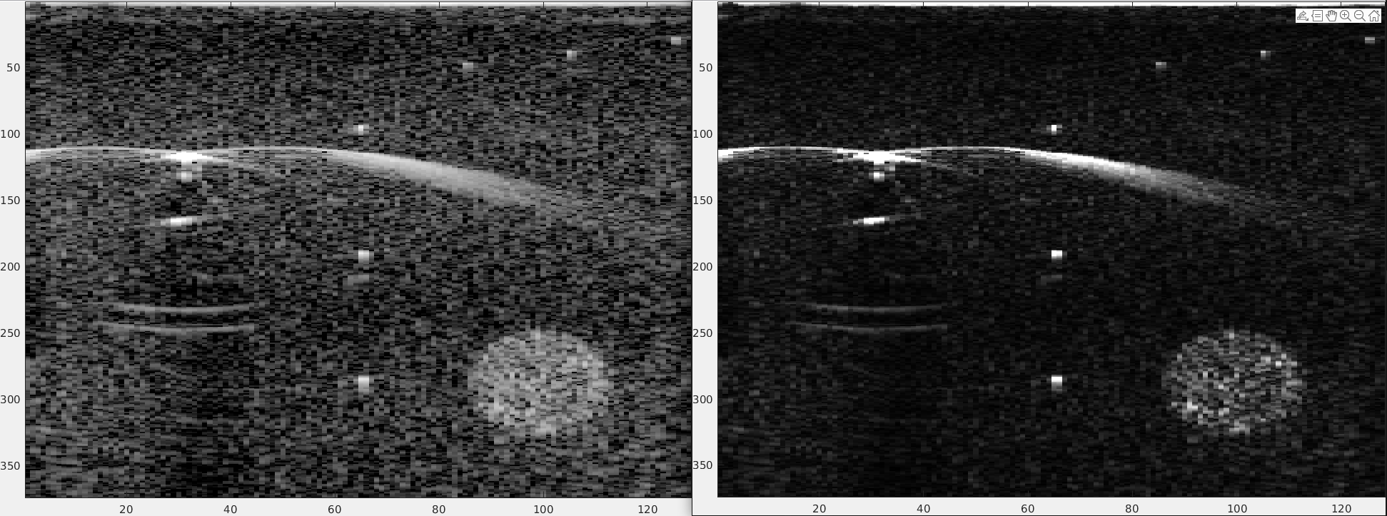
Effect of log: 1. compresses bright and weak relections into the same visual dynamic range. 2. Compresses speckle. 3. Turns the multiplicative effects of speckle into additive.
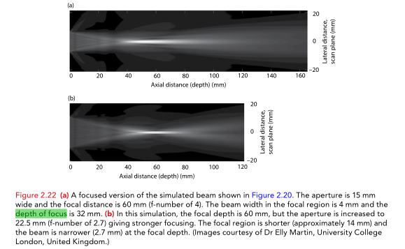
Lateral resolution with depth
\( LR = k \frac{F}{L}\lambda \)
where k depends on geometry and where beamwidth is measured.
Depth of focus:
\( d_F = 4\lambda (\frac{F}{L})^2 \)
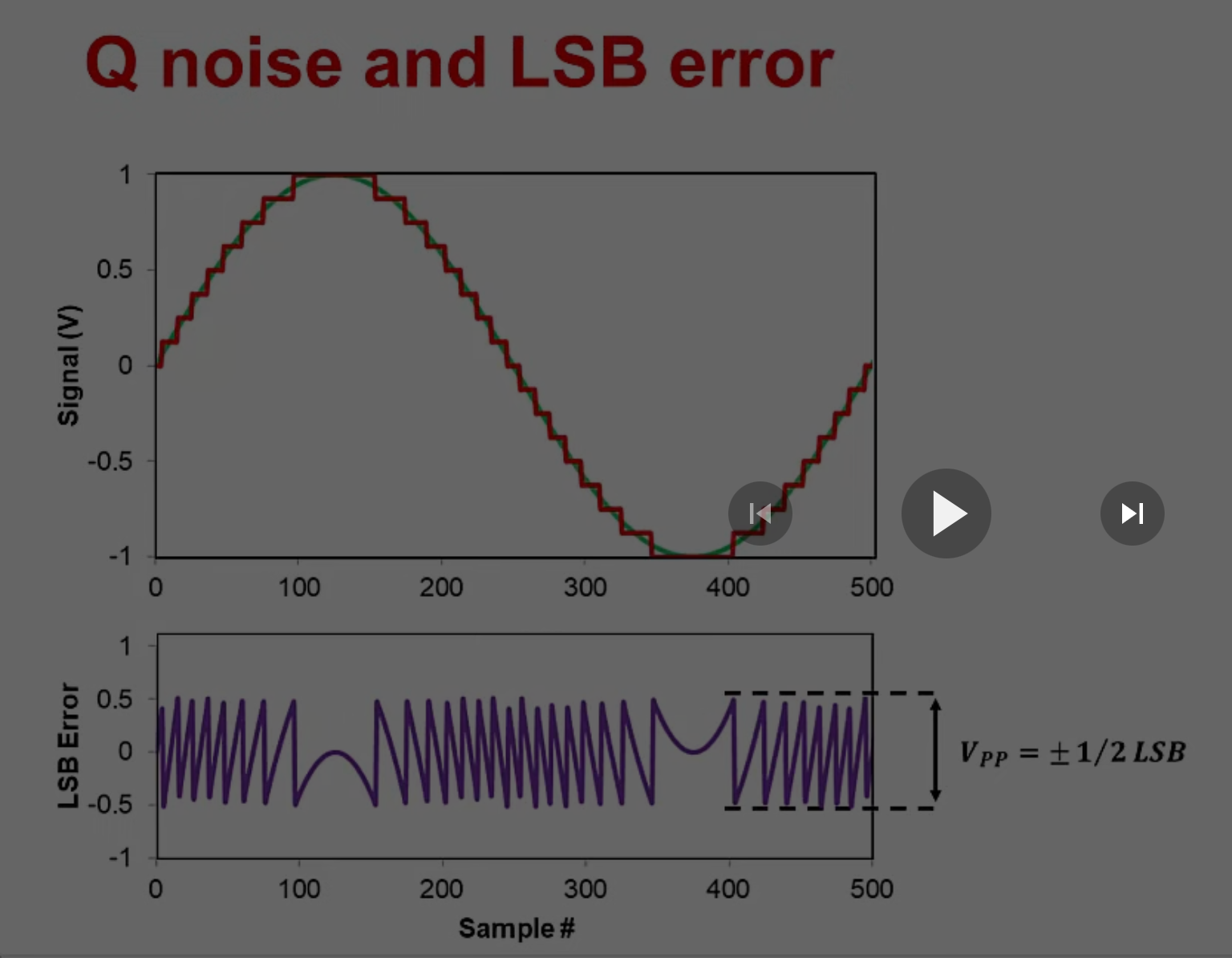
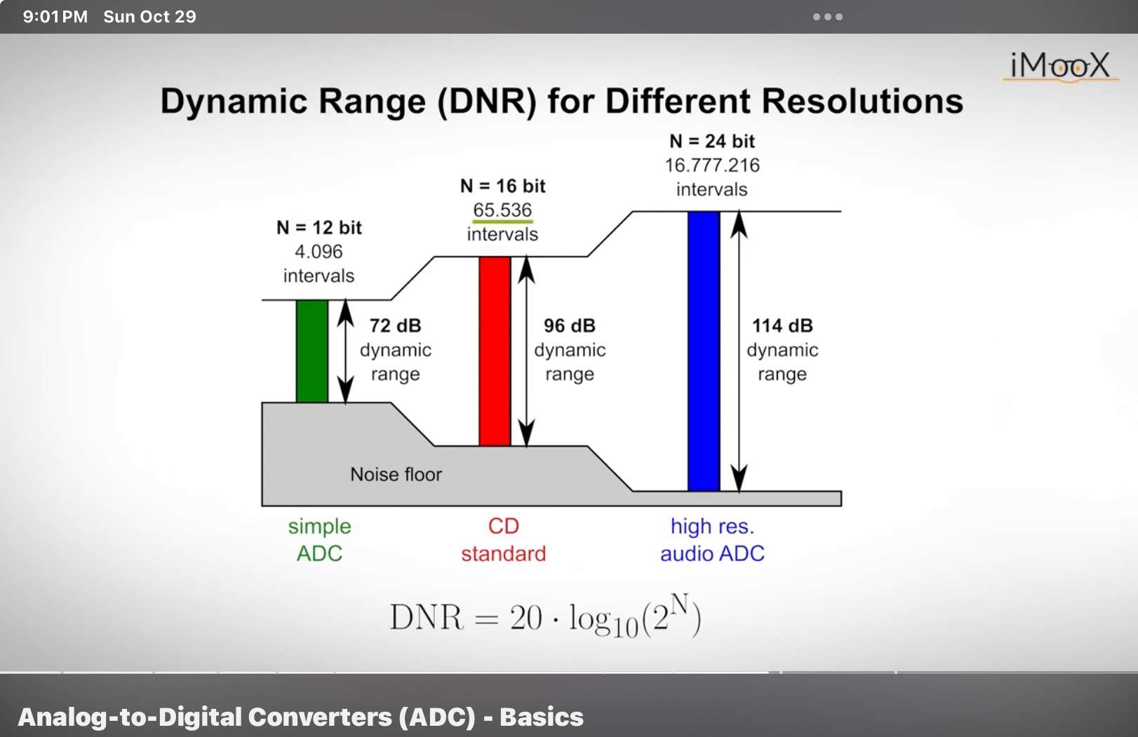
Dynamic range of signal
After mappng to RGB, images are ready to be displayed onto monitor. The cineloop is generally placed anywhere after after beamformation/IQ.
Main sources of noise
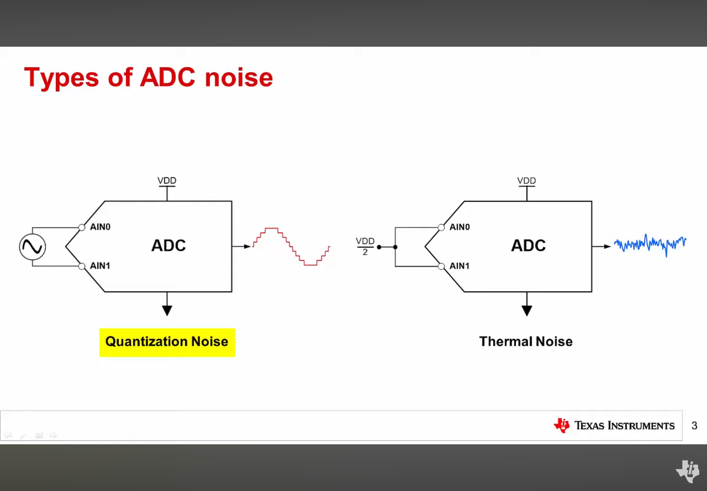
Electronic noise
After mappng to RGB, images are ready to be displayed onto monitor. The cineloop is generally placed anywhere after after beamformation/IQ.
Electronic noise