THE REVOLUTIONARY DUALMODE TRANSPORTATION SYSTEM
Chapter 12
Guidance and Switching
THE WAY IT IS DONE IN TRAINS AND AUTOMOBILES
Let’s examine the basics: The steel wheels on railroad cars have flanges on their inner faces. These flanges, bearing against the sides of the rails, apply side forces that keep the cars centered on the track. Trains are switched from one track to another by physically moving the ends of rails laterally several inches at track junctions. Lateral forces on the wheel flanges bearing against the switched rail ends forcefully turn the train to the selected track. Note that on railroads the engineers (drivers) do not guide or steer the trains in any way, someone on the ground or in a control room sets the switches.Automobiles are quite different in these respects. An automobile is guided and turned (switched) from one street to another by the driver steering the front wheels. This manual steering system requires constant attention and action on the part of the drivers. But automobiles can merge with traffic, and demerge from it at full speed, while individual cars in trains cannot, and whole trains cannot.
Some readers are now wondering, “Why does he bore us with simple stuff that we already know?” Yes we “know” it, but most of us haven’t really thought about it. Before we look for a better way of doing something we need to think about how it is being done now, thoroughly understand it, and ask ourselves why it is being done that way? What are the pros and cons of that method? After this kind of thorough “homework” we will be ready to intelligently look for a better way.
The old flanged-wheel-and-rail system has major limitations and dangerous faults. For one thing, the ends of rails must be physically moved before a train to be switched arrives at the intersection, and moved back to the through-traffic configuration after that train has passed. That system will therefore not permit fast closely spaced cars to be switched independently. Trains have to slow way down before they can switch tracks because of the crude mechanical joints present in that switching system. Even if the switching surfaces were perfect, the train couldn’t be switched at high speed, because the centrifugal forces generated would cause the cars to derail. And railroad accidents continue to occur because switches are sometimes left in the wrong position for oncoming trains. Note that railroad trains are guided and switched by the track, but automobiles are guided and switched from the car. With modern technologies there must be (and is) a far faster and safer switching method than the one used on railroads for over two-hundred years, and faster and safer than the steering system used on automobiles for over a hundred years.
THE GUIDEWAYS GUIDANCE AND SWITCHING SYSTEM
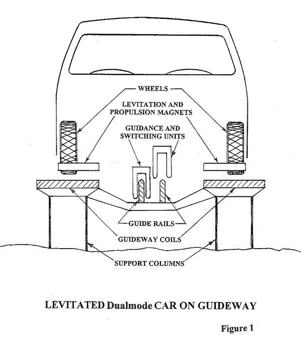
The levitated dualmode cars of the National System will need to switch safely at full guideway speed; and any car on a guideway must be able to automatically switch onto another guideway while cars very close ahead and behind it do not switch. Neither the railroad type of switching system nor the automobile type of switching system could fill that bill.To meet the above requirements, the author strongly advocates the following system: Provide two “guide rails” along the guideways in addition to the maglev that supports the vehicles. FIGURE 1 shows the end view of a guideway car on a guideway. Note the guide rail followers, which are part of the car. The two followers will be coupled together by a toggle linkage such that at any one time the car can engage either one of the guideway guide rails or the other, but never both and never neither.
The guide-rail followers won’t normally touch the guide rails, because maglev systems will provide the lateral guidance forces as well as the vertical vehicle-support forces. However, if for any reason the guidance maglev should “bottom out,” backup ball-bearing rollers will safely provide the vehicle guidance and switching forces. The tires on these rollers will be polyurethane or a comparable longwearing material, such as used on roller-blade skate wheels. The lateral guidance-force maglev will be of the inductive type, where the guide-rail followers contain permanent magnets, and the guide rails are of a structural, electrically conductive, but nonmagnetic material, such as aluminum alloy.
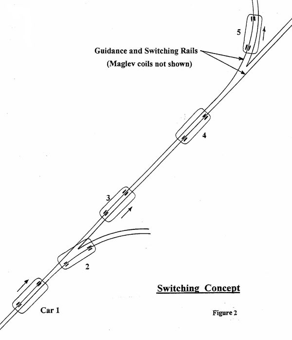
The two guide rails will be parallel with the guideway, and parallel with each other except at guideway intersections, as illustrated in FIGURE 2. At an intersection where a guideway branches, the left guide rail will follow the left branch and the right guide rail will follow the right branch. The navigation computer will provide commands to the guide-rail-follower mechanism in each car to route the car to its destination.
If the left guidance follower in a car is engaging the left guide rail that car will turn left or bear left at the next fork in the guideway. Whether or not a car will switch to a connecting guideway or go straight ahead through a junction will depend upon whether its left or its right guidance follower is engaging a guide rail.
The engagement and disengagement of the guide rail follower units will be commanded by the computer and accomplished automatically in each car as required to direct it to its destination. If a computer failure should cause the wrong guidance signal to be sent to a car, or to all cars, or if no signals are sent, some cars could be routed to the wrong guideways. But since the left and right followers will be mechanically prevented from being both engaged or both disengaged, no system errors or lapses in communication could cause accidents.
This type of guidance and switching system can operate at any speed and with any car spacing, but each car must be given the command for its particular routing long before a junction is reached. The higher the speed, the earlier the commands are needed. If we assume a maximum of one second is required to actuate the guidance followers in a car, at 60mph the switching signals would have to be received at least 90 feet before the cars reach the junction. On the 200mph guideways, the switching signals must be sent at least 300 feet before each car arrives at the junction. No problem.
Unlike the screeching and laterally lurching ride on trains during switching, a REV car will be quiet and smooth riding during switching, since it will have no physical contact with anything.
Different system innovators have chosen different details in designing guidance and switching systems of this type, so the systems look different from each other but they operate on the same principles for the same reasons. One guidance and switching system of this basic type has been safely routing cars daily on the Morgantown West Virginia “People Mover” since 1975. The author participated in the engineering design of that transportation system.
Next: CHAPTER 13
Automatic Parking
Back to: CONTENTS
Last modified: August 02, 2006