Automated Control of the Raytheon Personal Rapid Transit System
by Martin R. Batten and Edward C. Francis
Principal Engineers, Raytheon Company, 1001 Boston Post Road, Marlborough, Massachusetts, USA
April, 1997
Abstract
Raytheon and the Northeastern Illinois Regional Transportation Authority (RTA) have developed a prototype Personal Rapid Transit System (PRT). The system, PRT 2000™ employs four-passenger vehicles on an elevated guideway to provide direct origin-to-destination travel. A test track has been constructed at Raytheon's Marborough MA facility, and the program is currently proceeding through its testing phase. This test track is being used to demonstrate and prove the design for the mechanical, structural and control designs for the large scale PRT system. In the follow-on phase, a multi-loop, 7 station system is planned for deployment in Rosemont IL, a business community just outside of Chicago's O'Hare airport. This paper describes the Automatic Control System that manages the driverless vehicles. The functional breakdown and responsibilities of the control subsystems are discussed, as well as the computer architecture and data communications.
Automatic Vehicle Control Overview
PRT 2000™ operates with a highly responsive control system, custom developed by Raytheon to provide reliable and safe transit of passengers, delivering maximum system capacity by operating with a minimum distance between vehicles. This Automatic Vehicle Control (AVC) system has been developed based on the principles common to all Automatic Train Control (ATC) systems, following the new American Society of Civil Engineers (ASCE) Automatic People Mover (APM) standards, and specific requirements unique to this application. PRT 2000™ response times are fractions of a second, allowing vehicles to operate at headways as short as 2.5 seconds at 30 mph. Vehicle motion is continuously monitored and adjusted in real time to safely and efficiently merge streams of traffic where guideway sections join, and to properly switch vehicles toward their destination where a single guideway section diverges into two. Empty vehicles are automatically routed to stations where passenger demand exists.
PRT2000's™ AVC system is constructed in a three-level hierarchy. Every vehicle carries an on-board controller. These vehicle controllers receive direction from and report status to stationary wayside controllers, responsible for coordinating vehicle activities within fixed regions of the guideway. An RF data link mounted within the guideway structure allows continuous, high-bandwidth communications between the vehicle and wayside. The following figures depict a typical alignment and the partitioning of the control function to the distributed waysides.
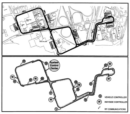
The wayside controllers are connected to each other via a high-speed fiber-optic network to coordinate vehicles transitioning from one region of guideway to the next. The fiber network extends to a central System Control Center (SCC), providing the System Control Operators with comprehensive status and oversight of the system's behavior. Within this modular, three-level computing hierarchy, PRT 2000's™ AVC system provides the functions required for the safe, automated control of vehicles. Automatic Vehicle Protection (AVP), Automatic Vehicle Operation (AVO) and Automatic Vehicle Supervision (AVS) functions are provided, in accordance with ASCE standards.
Automatic Vehicle Protection
AVP protects passengers, personnel and equipment from potentially hazardous situations; it has precedence over AVO and AVS functions. By reliably monitoring vehicle movement and equipment status within the system, AVP is able to revert the system to a safe state whenever a potentially hazardous condition is detected.
| PRT 2000's AVP Functions |
| Presence Detection |
| Separation Assurance |
| Unintentional Motion Detection |
| Overspeed Detection |
| Parted Consist Protection |
| Lost Signal Protection |
| Zero Speed Detection |
| Unscheduled Door Opening Protection |
| Door Control Protection Interlocks |
| Departure Interlocks |
| Direction Reversal Interlocks |
| Propulsion and Braking Interlocks |
| Switch Interlocks |
AVP autonomously monitors the position and speed of each vehicle, the state of its doors and door locks, and the state of its in-vehicle switch. The AVP system is based on a principle of permissive action; no action is permitted unless AVP can ensure it is safe. Continuous, positive action by AVP is required to allow vehicles to proceed along the guideway. As shown in the inset, a complete set of AVP functions is provided.
All processing associated with AVP is performed in parallel by a pair of redundant safety processors which are cross-checked for agreement. This agreement is a condition for any vehicle motion. A fail-safe hardware watchdog module on each vehicle keeps propulsion disabled and emergency braking engaged unless it receives periodic indication that its processors are operating correctly and the suite of safety checks they perform are all satisfied. In addition, the watchdog must receive regular assurance that communications with the wayside controller is functioning properly. In the wayside controller, a similar fail-safe architecture uses a hardware watchdog module to inhibit communications with vehicles unless it receives periodic indication that its safety processors are operating correctly and that their safety checks are satisfied.
All devices vital to safety are handled directly by AVP hardware and software. Safety-critical equipment sensors are triple redundant; a majority voting scheme provides for safe and reliable operation. AVO access to the door locks, the in-vehicle switch, and the parking brakes is via request to AVP. AVP satisfies a request only if it is safe to do so.
Automatic Vehicle Operation
AVO controls vehicles to provide automatic origin to destination passenger service between all stations in the system. This requires commanding the propulsion system to move the vehicle along the mainline guideway and within the stations, operating the in-vehicle switch to pursue a route to the vehicle's destination, and operating vehicle doors for boarding and deboarding. Vehicle movement is performed such that system capacity is maximized while observing all necessary constraints for safety and ride comfort. In particular, AVO operates the vehicles so that hazard protections are not invoked within AVP, which serves as the fail-safe monitor for the PRT 2000 control system.
AVO moves vehicles throughout the system in accordance with their destinations. Each vehicle carries its current destination with it as it travels, supplying it to the wayside controllers as part of its regularly reported status. Vehicle destinations change automatically as passenger trips begin and end, as empty vehicles are distributed, or as vehicles are added to or recalled from active service. The System Control Operator can also change vehicle destinations via manual intervention.
AVO controls the route that a vehicle takes to reach its destination by commanding its in-vehicle switch assembly either left or right each time the vehicle travels through a diverge region. Routing tables distributed by AVS to the wayside controllers provide the basis for AVO's positioning of the switch.
PRT 2000's off-line passenger stations allow vehicles to travel directly from their origin to their destination, bypassing all intermediate stations along the way. As the vehicle approaches its destination station, AVO manages its entrance to the station, assigns it a berth and precision aligns it. AVO applies the parking brake and holds the vehicle at zero speed until passenger boarding completes, then coordinates the exit of the vehicle from the station back out onto the mainline.
AVS provides automatic and System Control Operator (SCO) initiated system-wide monitoring and control capabilities. There are three sets of related responsibilities.
First, AVS compares system performance against established levels of service and automatically adjusts or controls the system to meet varying patron demands. Routing tables are distributed to each of the wayside controllers to specify the current best path to reach each destination. In most cases, all vehicles are given the same direction for a given destination, corresponding to the quickest path. However, in situations where there are multiple paths to the destination that may be traversed in approximately equal time, the system may specify that a percentage goes one way and the remaining percentage goes the other. Empty vehicle management instructions are specified for each station, based on demand. AVS controls audible and visual interfaces with patrons throughout the course of their interaction with the system, and controls the attendant ticket processing to initiate trips.
Second, AVS monitors vehicle traffic and equipment health, maintaining an active log of vehicle status, trip summary data, faults, and alarms. To the degree it can, AVS may also initiate certain automated fault recovery operations in response to unexpected events. For example, if one of the two redundant traction motors fail, AVS will automatically recall the vehicle from service after completing the current trip. As part of its system monitoring responsibility, AVS provides statistical accounting of trips and equipment usage to support ridership analysis and maintenance activities.
Finally, based on monitored system behavior and performance, AVS provides information to and accepts controls from the SCO to modify the automatic operations of the system or manually intervene in extraordinary circumstances. The SCO's role is primarily one of monitoring stations for safety and security, and responding to patron requests for assistance. At the same time, when an abnormal situation arises, AVS provides "human- in-the-loop" controls for fault management.
AVC Hardware Components
AVC computer and data communications hardware is distributed between the System Control Center, the wayside and the vehicles, providing the platform for AVP, AVO, and AVS functions. This hardware operates in conjunction with resident software and interfaces with other equipment to provide the required system level performance.
Vehicle Controller
One vehicle controller resides in each vehicle in a dual-redundant configuration; it is automatically reconfigured to continue to operate through hardware and software faults. The vehicle controller monitors and controls a myriad of subsystems in the vehicle, as depicted in the figure below:
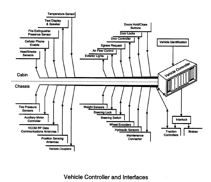
Each vehicle controller can sense and drive a vehicle's switches, annunciators, display, sensors and actuators and other supporting control/communication equipment by way of resident real-time operating software. The vehicle controller interfaces to the local wayside controller using its Vehicle Communications (VCOM) RF communication antennas. Two antennas mount on the chassis for bi-directional communication via the guideway antenna located on the left or right side.
The vehicle controller has a dual redundant architecture, containing two independent Vehicle Control Sets (VCS). Each VCS is an independent computer with a complete complement of I/O. Only one VCS is active at a time, with the active VCS controlling actuators and VCOM communication. The non-active VCS operates in a standby mode, ready to takeover if the active VCS goes down.
Within a VCS, a cross-checking pair of safety processors provides a safety-critical computing environment. Each member of the pair communicates with the other and issues a heartbeat at regular intervals to a watchdog module only after insuring its own health and that of its partner. If either both VCSs or the VCOM is deemed unhealthy, the watchdog module will stop the vehicle using the vehicle's propulsion / brake interlock.
Each vehicle carries a permanent unique code as a Vehicle ID which is accessible by software. This code is contained in an assembly that is permanently mounted in the cabin and is separate from the Controller.
Within the vehicle controller there is also a set of non-redundant hardware for non-safety-critical functions including controlling the vehicle doors and interfacing to the passengers with a text display and audio board.
Wayside Controller
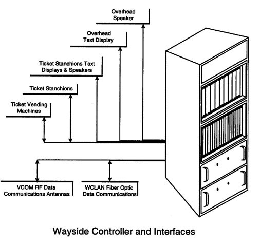
A wayside controller is configured to communicate to vehicles utilizing up to four separate communications antennas. Each single antenna spans a separate region of the guideway. Redundant hardware allows controllers to operate through single hardware failures. Interfaces to ticketing equipment, station signs, audio and other building equipment are provided, as depicted in the following figure.
Eight processors typically reside in a wayside controller. Four of the processors provide two redundant pairs that manage all the AVO and AVS functions. An additional four processors are used to provide safety-critical operations, configured as two cross-checking pairs. Each member of a safety pair communicates with the other and issues a heartbeat at regular intervals to a watchdog module only when it considers both itself and its corresponding processor to be healthy.
The watchdog module monitors the heartbeats from the four safety processors, and selects one pair to monitor the safe operation of the system. If, through the absence of heartbeats, the watchdog module determines that neither processor pair is healthy, the watchdog shuts down the VCOM region controlled by the wayside controller. The vehicle controller is designed to ensure that when VCOM messages cease, the vehicle is brought to a stop, guaranteeing a safe state.
Data Communications
Two distinct data communications services are provided by the PRT 2000™ AVC system. Data exchange between the vehicle controller and wayside controller is provided by an RF link that affords a non-contact mechanism for exchange between the moving vehicle and stationary wayside. Wayside to wayside communication is provided by a fiber-optic link that features the range and high-speed data rates required to manage the system. This fiber-optic link is also used by the System Control Center to communicate with all the waysides.
VCOM Overview
Wayside to vehicle communications is implemented using a 2.4GHz direct sequence spread spectrum communications link. The wayside radio modem communicates to the vehicle modem by radiating a signal via "leaky coaxial" cable that is mounted on the inside of the guideway to an antenna mounted on the vehicle that is held a few inches away from the cable. To accommodate guideway merges and provide a continuous communication link to the vehicle, the leaky coaxial cable can be mounted on the left or right of the guideway, and the vehicle carries two antennas which it can switch between, to select which cable to communicate over.
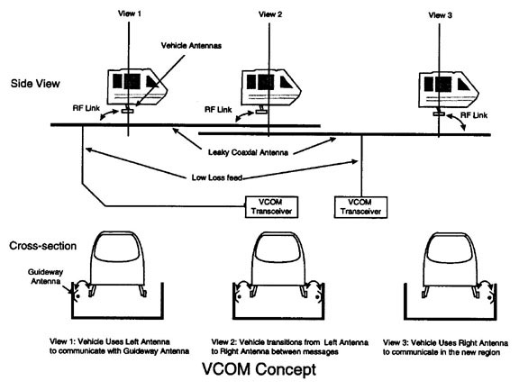
The vehicle coordinates switching antennas between messages, so no data is lost, and the guideway cable antenna incorporates overlapping regions to accommodate the distance the vehicle travels while coordinating this antenna switching. Low-loss feeds emanating from the Wayside connect the VCOM transceivers to the leaky coaxial cable in the guideway. Antennas on the chassis of the vehicle are used to pick off RF signals from the left or right of the guideway. This scheme is depicted in the figure. Each VCOM region is allocated a specific channel, and as the vehicle passes through VCOM regions, it is coordinated to change channels just prior to the transfer. This avoids one VCOM region interfering with its neighbors.
WCLAN Overview
The Wayside Controller Local Area Network (WCLAN) comprises two separate, redundant networks that connect to the same wayside controllers and System Control Center workstations through separate Fiber-optic Distributed Data Interface (FDDI) cards. Each of the redundant networks complies with the FDDI standards. They utilize fiber- optic technology as the primary data-carrying medium. Dependent upon the complexity of an alignment, each of the FDDI networks may use one or several centralized distribution points implemented via concentrator units (or hubs). In a large system, when several concentrators are used, they are connected by a main ring of the FDDI Network (referred to here as the Backbone ring). Each concentrator provides connections to the wayside controllers and System Control Center through FDDI controllers. System Control Center The System Control Center (SCC) hardware supports the AVS functions in the system. It is used to provide interaction between the System Operator and the various PRT 2000™ elements. The SCC communicates to the wayside controllers using the WCLAN.
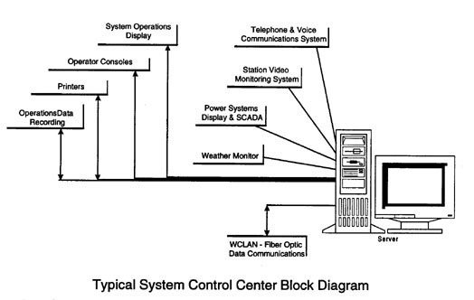
Each System Control Center is site specific. Typical SCC equipment includes commercial workstations used as servers, from which System Control Operators at multiple graphical display workstations can monitor and control the system. Specialized System Operational Displays, a SCADA system, weather station, data recorders and printers, voice communications and security monitoring equipment are added to this basic computer network as required for each specific installation. The workstations all interface to the data servers which redundantly communicate with the wayside controllers via the WCLAN network. The System Control Center provides recording of commands, messages, alarms, and all information with date and time of transmissions between the wayside controllers, vehicles and the SCC. Equipment is contained in an environmentally controlled building and receives power from an uninterruptible power source.
Summary
Three and one-half years into the development program for the PRT 2000™ system, Raytheon and the Northeastern Illinois RTA are seeing the culmination of their efforts to design a truly personal rapid transit system. The opportunity to ride the prototype vehicle at the Raytheon Marlborough, MA, test site is the most convincing evidence that the technology is readily available and capable. Significant advances have recently been made in packaging the required computing power into smaller volumes and making it cost effective for this type of distributed application. Leveraging from this state-of-the-art, an automatic control system capable of safely and efficiently operating a fleet of small vehicles at headways of just a few seconds has been developed. The AVC system is full-featured. In following the ASCE standards for APMs, the control system incorporates the legacy of safety and practical experience developed by the transit industry. It is modular, which permits small initial alignments to evolve into large networks as they become established. It uses commercially available equipment and software development tools, insuring it is cost effective. Upon completion of its extensive test and evaluation program, the PRT2000™ AVC system will provide safe, efficient, and reliable control of personnel rapid transit systems in real world applications.